CAPINTEC, INC. CAPRAC
®
-t
4-4 SYSTEM SETUP April 2021
System Assembly
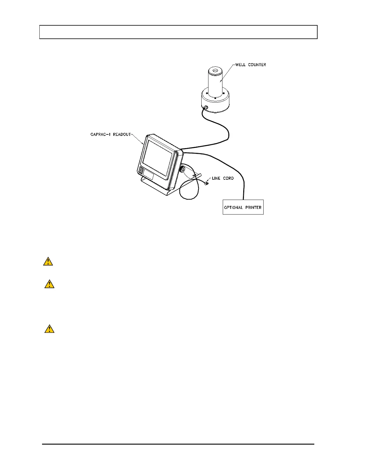
Figure 4-2 Complete System
1. Verify that all power switches (Readout, Printer) are in the “OFF” or “0” position.
(Note: If using the Slip-Ticket printer, please unplug from AC Power.)
CAUTION: Position the device such that access the supply mains disconnect
switch on the rear of the CRC
®
-55t Readout is not obstructed.
CAUTION: Only specified or certified accessories shall be used and connected to
the Well Counter.
2. Connect the Well Counter Cable to the connector at the rear of the CAPRAC
®
-t
Readout labeled “WELL COUNTER”.
CAUTION: To avoid damage, do not over-tighten the screws on the Cable
connector. The screws should be finger-tightened only!
3. Attach the Power Cable to the receptacle on the Power Module located on the back
of the Readout Unit.
Note: The power entry module switch located on the rear of the CRC
®
-55t provides a
quick and easy method to disconnect supply mains.
Note: Do not place the Readout unit against a wall or other object so that the power
cord can be detached from the back of the Readout unit.
4. If the optional printer is an RS-232 (serial) version, attach the printer cable (one end
has a 9 pin “D” connector, the other end has a 25 pin “D” connector) to the 9 pin “D”