14.
Install the VNR (5.4). •
15.
Plug the power cord into the rear of the VNR.
16.
Reconnect the chassis power cord to a proper electrical outlet and power-up the system.
17.
Verify system operation (Section 4).
5.10 INTERNAL CPU CHASSIS VNR HARNESS
5.10.1 Removal of the Internal CPU Chassis VNR Harness
1.
Power-down the system and disconnect the chassis power cord from the ac electrical outlet (5.3).
2.
Unplug the power cord from the rear of the VNR.
3.. Loosen the fastener on the right side of the VNR and swing the VNR away from the back panel.
4.
Loosen the two bulkhead fasteners on the rear connector bulkhead and swing the bulkhead down.
5.
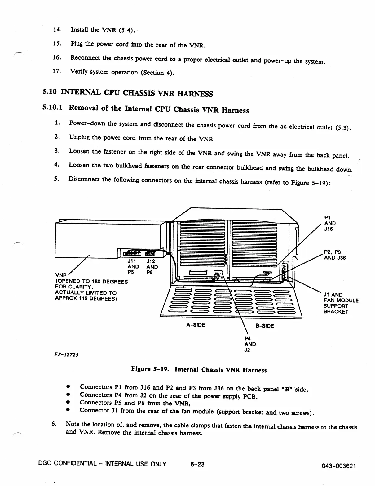
Disconnect the following connectors on the internal chassis harness (refer to Figure 5-19):
P1
AND
J16
VNR
J11
J12
AND AND
P5
P6
(OPENED TO 180 DEGREES
FOR CLARITY.
ACTUALLY LIMITED TO
APPROX 115 DEGREES)
P2, P3,
AND J36
/ 1::=3 .1===2 • C==> C==> C==:2
/ C===> e
2. • .4==> 4:=:=
1
.
c===>
J1 AND
r
.0 c===• -fir-- c===
,
c===> c===.
FAN MODULE
c===> c===•
.1==> • e===•
SUPPORT
c===> c===> 4r:===> —!--- c===> c===>
c===> g===:> f===> ---- t
.> r
x
BRACKET
A
-
SIDE
B-SIDE
P4
AND
J2
FS-12723
Figure
5-19.
Internal Chassis VNR Harness
•
Connectors P1 from J16 and P2 and P3 from J36 on the back panel "B" side,
•
Connectors P4 from J2 on the rear of the power supply PCB,
•
Connectors P5 and P6 from the VNR,
•
Connector J1 from the rear of the fan module (support bracket and two screws).
6. Note the location of, and remove, the cable clamps that fasten the internal chassis harness to the chassis
and VNR. Remove the internal chassis harness.
DGC CONFIDENTIAL - INTERNAL USE ONLY
5-23
043-003621