4
'
L....1 1.
L
111
E
SAVD
SWITCH
PS
SW1
111
0
P7
P3
P6
P1
FS-12740
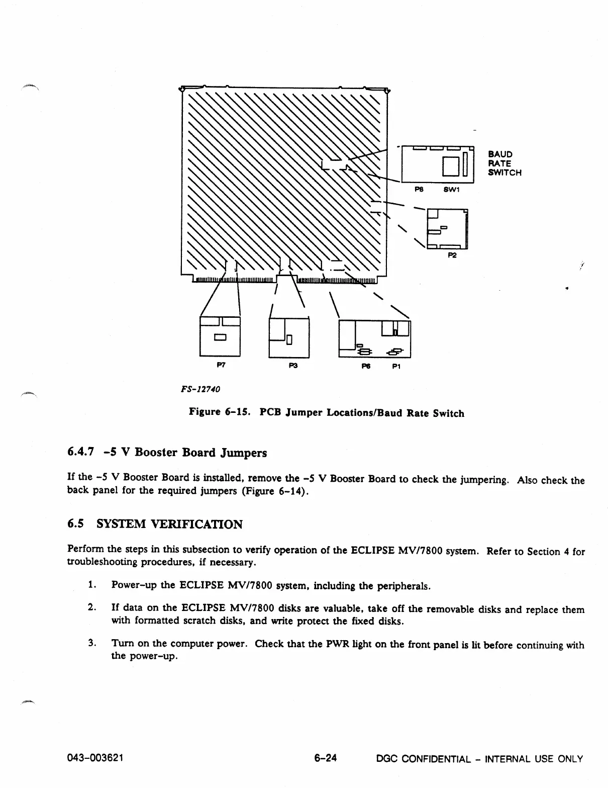
Figure 6-15. PCB Jumper Locations/Baud Rate Switch
6.4.7 —5 V Booster Board Jumpers
If the -5 V Booster Board is installed, remove the -5 V Booster Board to check the jumpering. Also check the
back panel for the required jumpers (Figure 6-14).
6.5 SYSTEM VERIFICATION
Perform the steps in this subsection to verify operation of the ECLIPSE MV17800 system. Refer to Section 4 for
troubleshooting procedures, if necessary.
1.
Power-up the ECLIPSE MV/7800 system, including the peripherals.
2.
If data on the ECLIPSE MV/7800 disks are valuable, take off the removable disks and replace them
with formatted scratch disks, and write protect the fixed disks.
3.
Turn on the computer power. Check that the PWR light on the front panel is lit before continuing with
the power-up.
043
-
003621
6
-
24
DGC
CONFIDENTIAL - INTERNAL USE ONLY