SECTION 2
OPERATING CONTROL AND PROCEDURES
The operator interacts with the ECLIPSE MV/7800 and MV/8700-C computers via the system control panel and
the system terminal. This section describes these controls and how to use them to power-up, reset, and
power-down the system. It also describes all indicators and system terminal modes of operation. The MV/7800
has a resident COMSWITCH-II. COMSWITCH-II operating instructions start at subsection 2.8.
2.1 CPU CHASSIS CONTROL PANEL
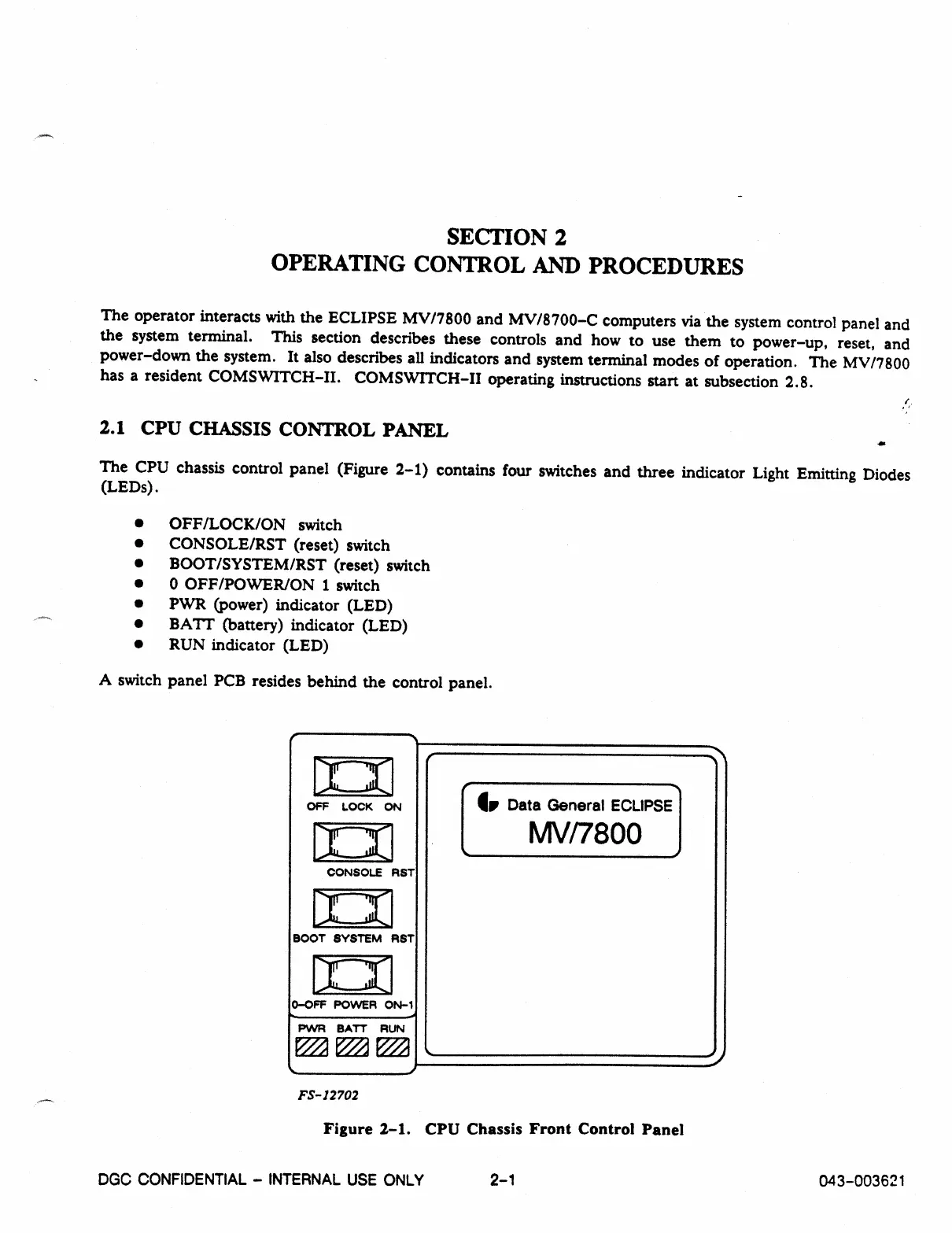
The CPU chassis control panel (Figure 2-1) contains four switches and three indicator Light Emitting Diodes
(LEDs).
•
OFF/LOCK/ON switch
•
CONSOLE/RST (reset) switch
•
BOOT/SYSTEM/RST (reset) switch
•
0 OFF/POWER/ON 1 switch
•
PWR (power) indicator (LED)
•
BATT (battery) indicator (LED)
•
RUN indicator (LED)
A switch panel PCB resides behind the control panel.
OFF LOCK
ON
104
CONSOLE RST
BOOT SYSTEM RST
D-OFF POWER ON-1
PVVR BATT RUN
1.
Data General ECLIPSE
MV/7800
FS-12702
Figure 2-1. CPU Chassis Front Control Panel
DGC CONFIDENTIAL - INTERNAL USE ONLY
2-1
043-003621