5.5 FAN AND FAN MODULE
The individual fan should be replaced when
a
fan failure occurs. To determine which fan has failed on the CPU
chassis after a code two fault, turn the POWER switch to OFF, then ON. The failing fan will be noisy or not run.
5.5.1 Removal of Fan Module and Fans
1.
Power-down the system and unplug the ac source.
2.
Remove the decorative front panel (5.1) and the RFI shield (5.2).
3.
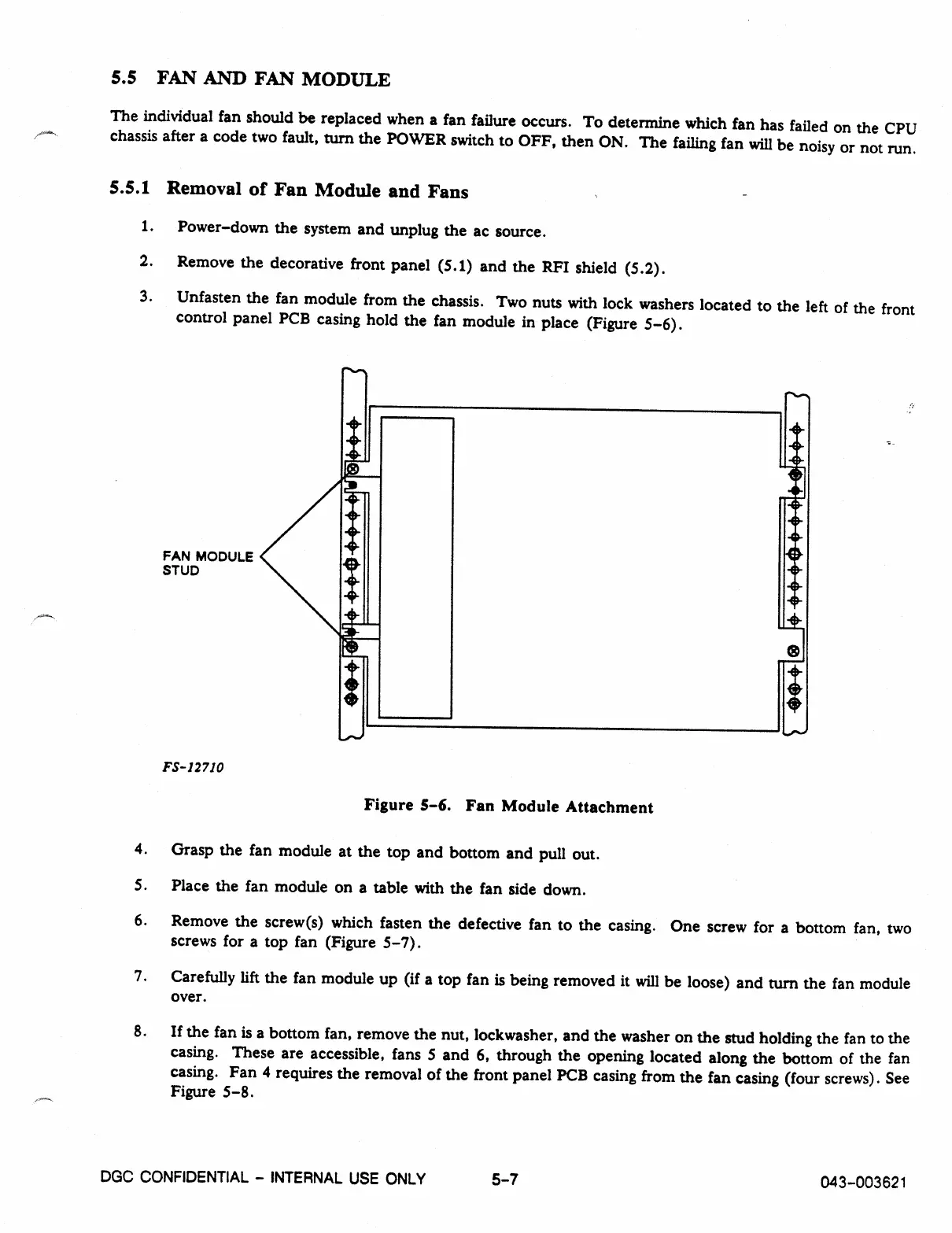
Unfasten the fan module from the chassis. Two nuts with lock washers located to the left of the front
control panel PCB casing hold the fan module in place (Figure 5-6).
FAN MODULE
STUD
FS- 12710
Figure 5-6. Fan Module Attachment
4. Grasp the fan module at the top and bottom and pull out.
S. Place the fan module on a table with the fan side down.
6.
Remove the screw(s) which fasten the defective fan to the casing. One screw for a bottom fan, two
screws for a top fan (Figure 5-7).
7.
Carefully lift the fan module up (if a top fan is being removed it will be loose) and turn the fan module
over.
8.
If the fan is a bottom fan, remove the nut, lockwasher, and the washer on the stud holding the fan to the
casing. These are accessible, fans 5 and 6, through the opening located along the bottom of the fan
casing. Fan 4 requires the removal of the front panel PCB casing from the fan casing (four screws). See
Figure 5-8.
DGC CONFIDENTIAL - INTERNAL USE ONLY
5-7
043-003621