2.1.1 Switches
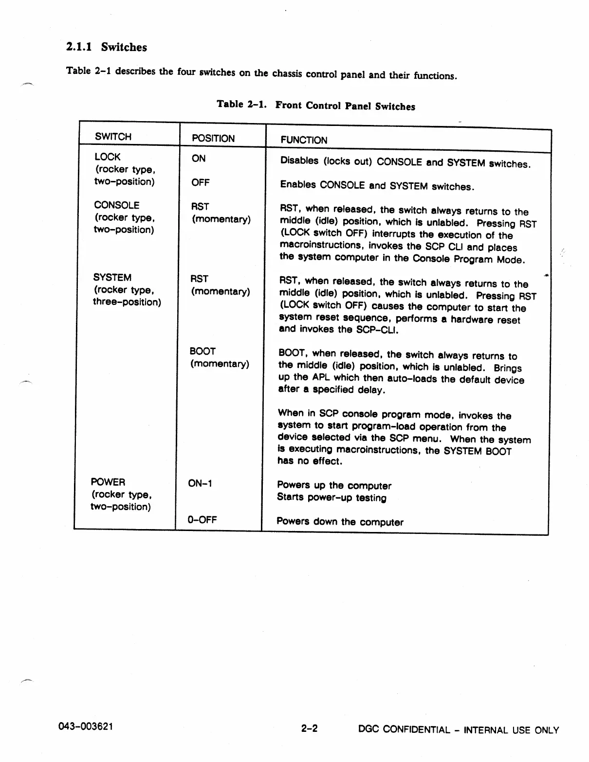
Table 2-1 describes the four switches on the chassis control panel and their functions.
Table 2-1. Front Control Panel Switches
SWITCH
I
POSITION
I
FUNCTION
LOCK
(rocker type,
ON
Disables (locks out) CONSOLE and SYSTEM switches.
two-position)
OFF
Enables CONSOLE and SYSTEM switches.
CONSOLE
RST
RST, when released, the switch always returns to the
(rocker type,
two-position)
(momentary)
middle (idle) position, which is unlabled.
Pressing RST
(LOCK switch OFF) interrupts the execution of the
macroinstructions, invokes the SOP CLI and places
the system computer in the Console Program Mode.
SYSTEM
RST
AST, when released, the switch always returns to the
(rocker type,
(momentary)
middle (idle) position, which is unlabled. Pressing RST
three-position) (LOCK switch OFF) causes the computer to start the
system reset sequence, performs a hardware reset
and invokes the SCP-CLI.
BOOT
BOOT, when released, the switch always returns to
(momentary)
the middle (idle) position, which is unlabled. Brings
up the APL which then auto-loads the default device
after a specified delay.
When in SOP console program mode, invokes the
system to start program-load operation from the
device selected via the SOP menu. When the system
Is executing macroinstructions, the SYSTEM BOOT
has no effect.
POWER
ON-1
Powers up the computer
(rocker type,
Starts power-up testing
two-position)
0-OFF
Powers down the computer
043-003621
2-2
DGC CONFIDENTIAL -
INTERNAL USE ONLY