2. Power down the system.
3. Remove internal System Terminal Interface cable 005-019213. Disconnect plug P17 from backplane
connector J17 and D-25 connector from the bulkhead.
4. Install the replacement internal System Terminal Interface MV17800 COMSWITCH-II cable
005-025369 as follows:
a.
Connect cable 005-025369 backplane connector to the A-side of the backplane as shown in Figure
6-19. Pin 1 is on the left side of the backplane connector. The connector will be marked
"P1-A-SIDE".
b.
Connect the second end of the internal MV/7800 COMSWITCH-H cable to the lower left corner
of the bulkhead or to the same bulkhead location where the old cable connector was removed
from.
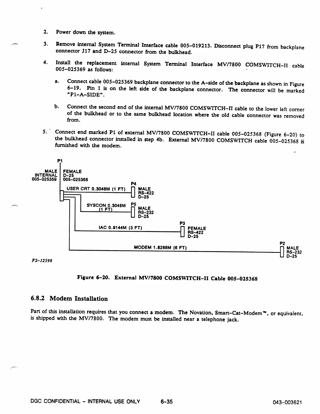
5. Connect end marked P1 of external MV/7800 COMSWITCH-II cable 005-025368 (Figure 6-20) to
the bulkhead connector installed in step 4b. External MV/7800 COMSWITCH cable 005-025368
is
furnished with the modem.
P1
MALE FEMALE
INTERNAL D-25
005-025359 005-025368
P4
USER CRT 0.3048M (1 FT)
fl
MALE
RS-422
D-25
SYSCON 0.3048M PS
(1 FT)
0 MALE
RS-232
D-25
FS-12598
P3
IAC 0.9144M (3 FT)
1111 FEMALE
RS-422
D-25
MODEM 1.8288M (6 FT)
P2
fl
MALE
RS-232
D-25
Figure 6-20. External MV/7800 COMSWITCH-II Cable 005-025368
6.8.2 Modem Installation
Part of this installation requires that you connect a modem. The Novation, Smart-Cat-Modem', or equivalent,
is shipped with the MV/7800. The modem must be installed near a telephone jack.
DGC CONFIDENTIAL - INTERNAL USE ONLY
6
-
35
043-003621