c.
[.
N
J
-
71
)
00
L
- -
\:=.2_
1
-turtmo
0
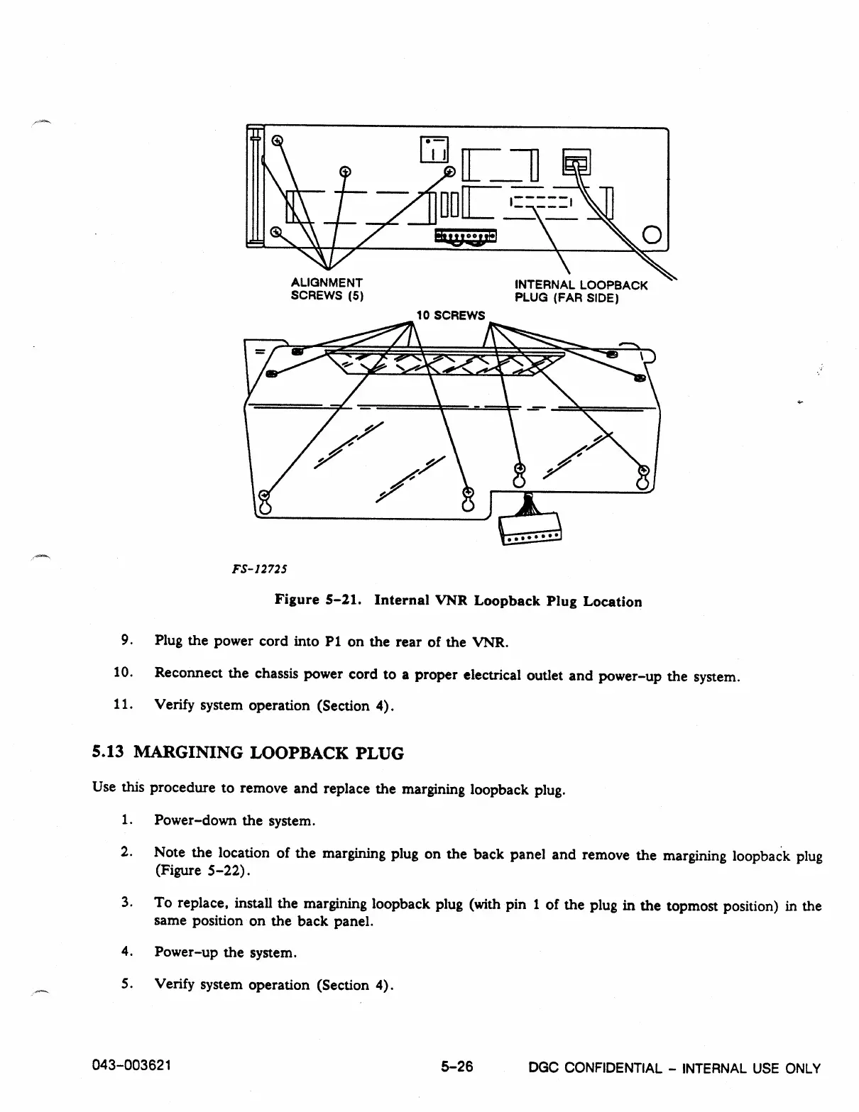
ALIGNMENT
INTERNAL LOOPBACK
SCREWS (5)
PLUG (FAR SIDE)
10 SCREWS
FS-12725
Figure 5-21. Internal VNR Loopback Plug Location
9.
Plug the power cord into P1 on the rear of the VNR.
10.
Reconnect the chassis power cord to a proper electrical outlet and power-up the system.
11.
Verify system operation (Section 4).
5.13 MARGINING LOOPBACK PLUG
Use this procedure to remove and replace the margining loopback plug.
1.
Power-down the system.
2.
Note the location of the margining plug on the back panel and remove the margining loopback plug
(Figure 5-22).
3.
To replace, install the margining loopback plug (with pin 1 of the plug in the topmost position) in the
same position on the back panel.
4.
Power-up the system.
5.
Verify system operation (Section 4).
043-003621
5-26
DGC CONFIDENTIAL - INTERNAL USE ONLY