6.8.5 Modem Connection
Perform the following instructions to cable the Novation Modem to the host system.
1.
Ensure that the modem ON/OFF power switch is in the OFF position.
2.
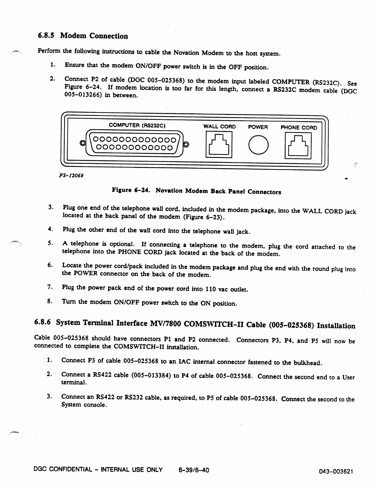
Connect P2 of cable (DGC 005-025368) to the modem input labeled COMPUTER (RS232C). See
Figure 6-24. If modem location is too far for this length, connect a RS232C modem cable (DGC
005-013266) in between.
COMPUTER (RS232C)
WALL CORD POWER PHONE CORD
0000000000000)
0
irf-111
000000000000
FS- 12068
Figure 6-24. Novation Modem Back Panel Connectors
3.
Plug one end of the telephone wall cord, included in the modem package, into the WALL CORD jack
located at the back panel of the modem (Figure 6-23).
4.
Plug the other end of the wall cord into the telephone wall jack.
5.
A telephone is optional. If connecting a telephone to the modem, plug the cord attached to the
telephone into the PHONE CORD jack located at the back of the modem.
6.
Locate the power cord/pack included in the modem package and plug the end with the round plug into
the POWER connector on the back of the modem.
7.
Plug the power pack end of the power cord into 110 vac outlet.
8.
Turn the modem ON/OFF power switch to the ON position.
6.8.6 System Terminal Interface MV/7800 COMSVVITCH-II Cable (005-025368) Installation
Cable 005-025368 should have connectors P1 and P2 connected. Connectors P3, P4, and P5 will now be
connected to complete the COMSWITCH-II installation.
1.
Connect P3 of cable 005-025368 to an IAC internal connector fastened to the bulkhead.
2.
Connect a RS422 cable (005-013384) to P4 of cable 005-025368. Connect the second end to a User
terminal.
3.
Connect an RS422 or RS232 cable, as required, to P5 of cable 005-025368. Connect the second to the
System console.
DGC CONFIDENTIAL -
INTERNAL USE ONLY
6-3916-40
043-003621