3.
Press the snap fastener of the straight cord onto any of the four snaps of the black mat until the snap
fastener is firmly in place.
4.
Take the alligator clip on the other end of the straight cord and clip it to the chassis frame of the
ECLIPSE MV/7800.
NOTE
The alligator clip must be attached to a metal portion of the chassis,
avoid painted surfaces.
5.
Place the wrist band around either wrist with the gray side against the skin. Be sure that the metal
portion behind the button makes snug contact with the skin.
NOTE
Both wrist bands included with each ESD kit are identical except for size.
The blue band is slightly larger than the beige band. Use the band that
fits snugly.
6.
Press the yellow resistor end of the coil type cord onto the wrist band snap.
7.
Clip the alligator clip at the other end of the coil type cord to the edge of the black mat.
The ESD kit is now installed and the PCBs can now be removed, handled, and installed.
5.8 PLUG-IN PCB
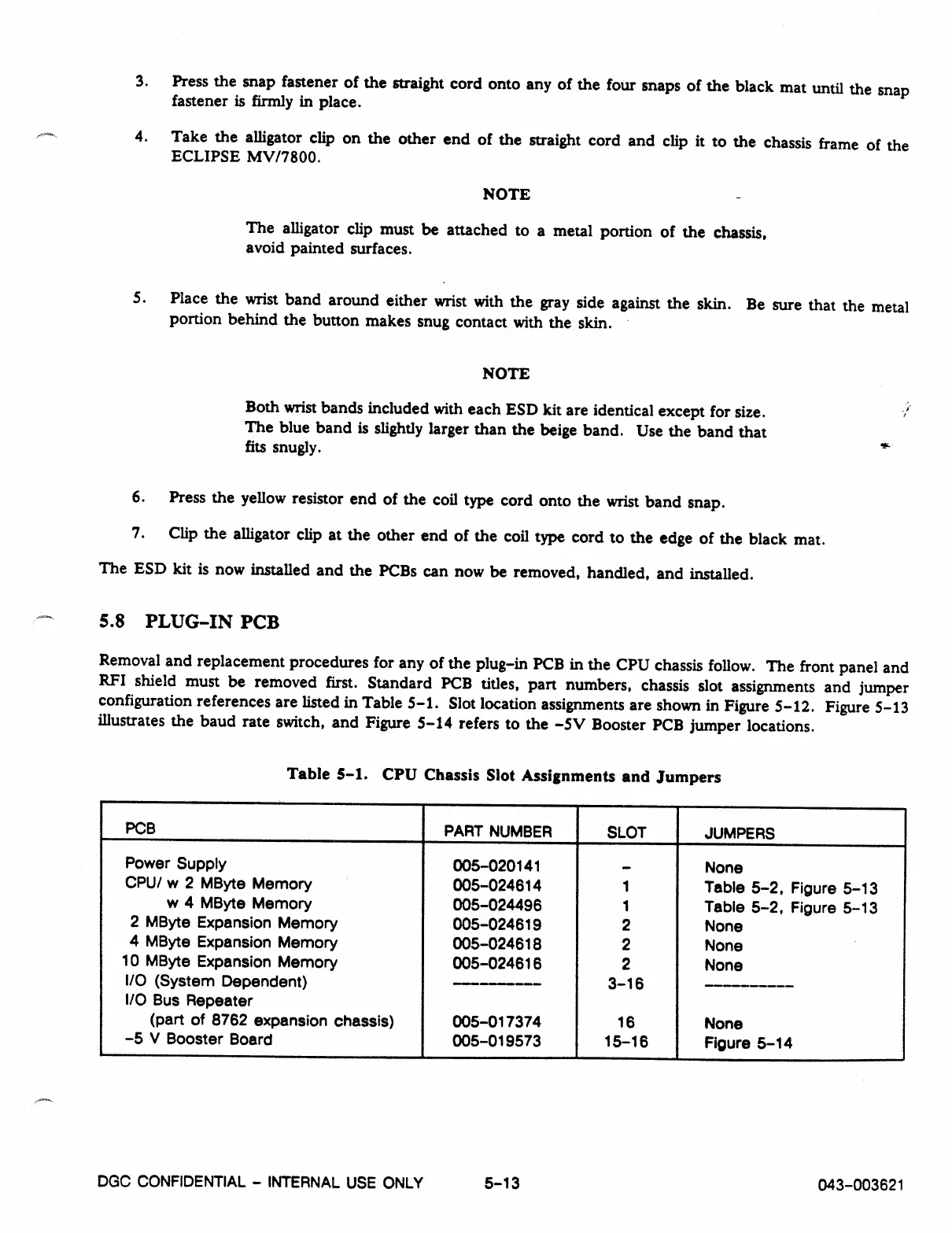
Removal and replacement procedures for any of the plug-in PCB in the CPU chassis follow. The front panel and
RFI shield must be removed first. Standard PCB titles, part numbers, chassis slot assignments and jumper
configuration references are listed in Table 5-1. Slot location assignments are shown in Figure 5-12. Figure 5-13
illustrates the baud rate switch, and Figure 5-14 refers to the -5V Booster PCB jumper locations.
Table 5-1. CPU Chassis Slot Assignments and Jumpers
PCB
PART NUMBER
SLOT
JUMPERS
Power Supply
005-020141
-
None
CPU/ w 2 MByte Memory
005-024614
1
Table 5-2, Figure 5-13
w 4 MByte Memory
005-024496
1
Table 5-2, Figure 5-13
2 MByte Expansion Memory
005-024619
2
None
4 MByte Expansion Memory
005-024618
2
None
10 MByte Expansion Memory
005-024616
2
None
I/O (System Dependent)
--------
3-16
I/O Bus Repeater
(part of 8762 expansion chassis)
005-017374
16
None
-5 V Booster Board
005-019573
15-16
Figure 5-14
DGC CONFIDENTIAL - INTERNAL USE ONLY
5-13
043-003621