Table 6-1. Line Voltage Specifications
VOLTAGE
(Vac)
FREQUENCY
(Hz)
PHASE
CONNECTION
ACCEPTABLE MARGINS
VOLTAGE (Vac)
FREQUENCY (Hz)
120/208
60
WYE
102-132/177-229
60 +/- 0.5
100/200
50
DELTA
90-110/180-220
50 +/- 0.5
220
50
DELTA
187-242
50 +/- 0.5
240
50
DELTA
204-264
50 +/- 0.5
220/380
50
WYE
187-242/323-418
50 +/- 0.5
240/415
50
WYE
204-264/354-459
50 +/- 0.5
* Single Phase Voltage
** Phased Voltage
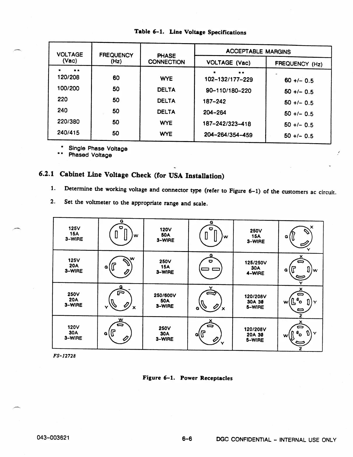
6.2.1 Cabinet Line Voltage Check (for USA Installation)
1.
Determine the working voltage and connector type (refer to Figure 6-1) of the customers ac circuit.
2.
Set the voltmeter to the appropriate range and scale.
125V
15A
3-WIRE
0
0
w
120V
50A
9-WIRE
co
0 a
w
250V
15A
3-WIRE
U
._..%
v
125V
20A
3-WIRE
W
250V
15A
3-WIRE
.-
0
o o
125/250V
30A
4-WIRE
c=,
a
3
D
C:=)
250V
20A
3-WIRE
.-
trz,
%
8
250/600V
50
A
3-WIRE
c=.
I
%
o
x
120/208V
30A 3$
5-WIRE
c=,
w I
G
o
0
c=1
120V
30A
3-WIRE
T
,,
250V
30A
3-WIRE
120/208V
20A 30
5-WIRE
g
Go
t
c:t.
FS- 12728
Figure 6-1. Power Receptacles
043-003621
6-6
DGC CONFIDENTIAL - INTERNAL USE ONLY