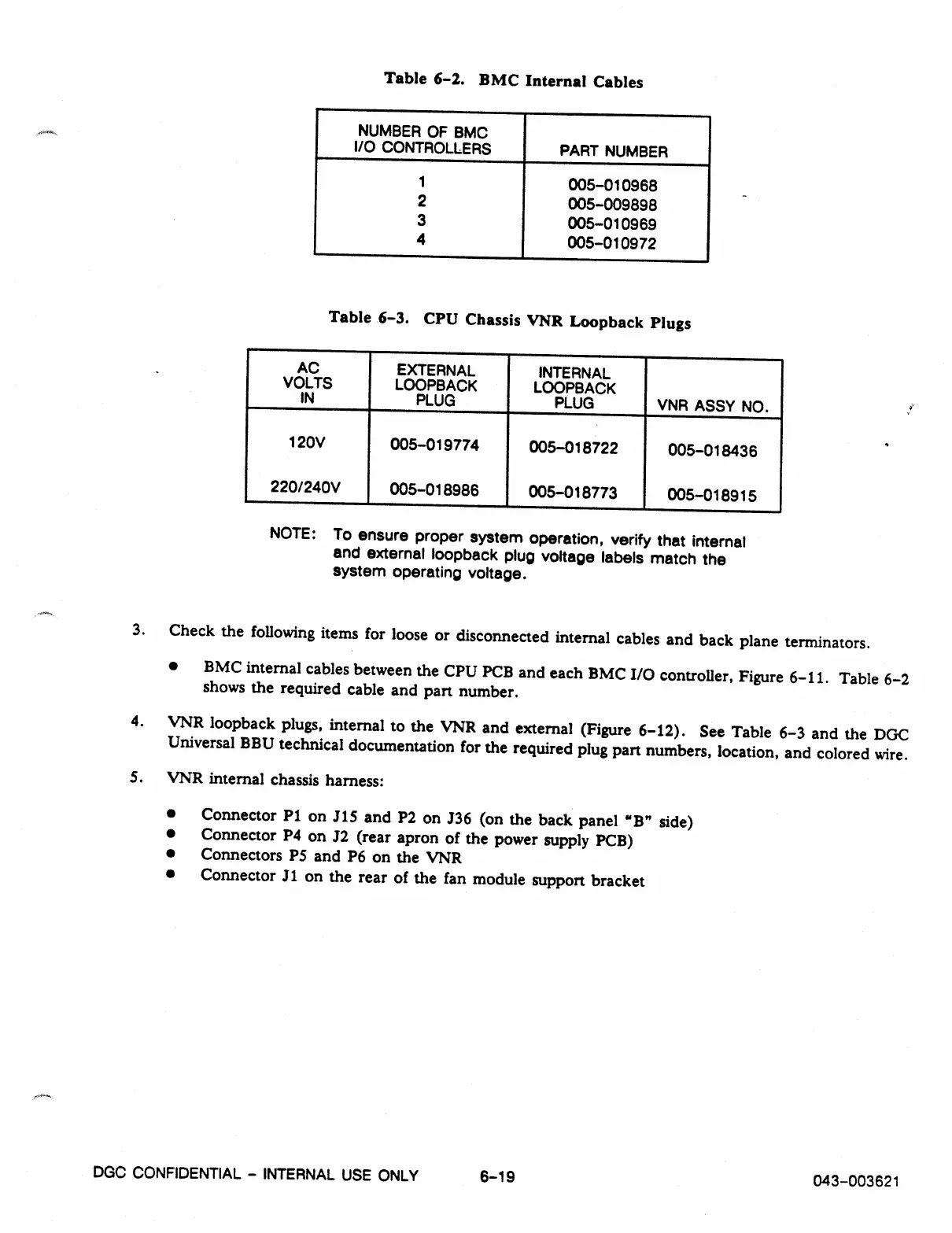
Table 6-2. BMC Internal Cables
NUMBER OF BMC
I/O CONTROLLERS
PART NUMBER
1
005-010968
2
005-009898
3
005-010969
4
005-010972
Table 6-3. CPU Chassis VNR Loopback Plugs
AC
VOLTS
IN
EXTERNAL
LOOPBACK
PLUG
INTERNAL
LOOPBACK
PLUG
VNR ASSY NO.
120V
220/240V
005-019774
005-018986
005-018722
005-018773
005-018436
005-018915
NOTE: To
ensure proper system operation, verify that internal
and external loopback plug voltage labels match the
system operating voltage.
3. Check the following items for loose or disconnected internal cables and back plane terminators.
•
BMC internal cables between the CPU PCB and each BMC I/O controller, Figure 6-11. Table 6-2
shows the required cable and part number.
4.
VNR loopback plugs, internal to the VNR and external (Figure 6-12). See Table 6-3 and the DGC
Universal BBU technical documentation for the required plug part numbers, location, and colored wire.
5.
VNR internal chassis harness:
•
Connector P1 on J15 and P2 on J36 (on the back panel "B" side)
•
Connector P4 on J2 (rear apron of the power supply PCB)
•
Connectors P5 and P6 on the VNR
•
Connector J1 on the rear of the fan module support bracket
DGC CONFIDENTIAL - INTERNAL USE ONLY
6-19
043-003621