46 Magellan™ 9300i / 9400i Scanners
Remote Display Cabling
Your installation should also take into account the routing of Remote Display
cabling. Ensure that distance and obstacles spanned by the routed cable will
not kink, pinch or stretch it. Also keep in mind you may need to drill a hole
through which to route it.
Placing and Installing the Remote Display
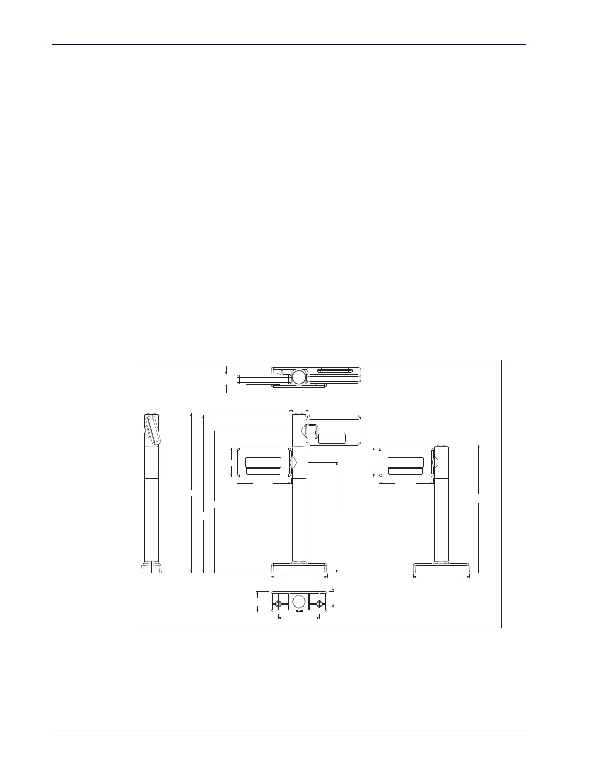
1. Determine where you want to install the Remote Scale Display based on
your counter design, the viewing angle, lighting considerations and cable
routing discussed previously. Reference
Figure 26 for the display’s physi-
cal dimensions. Optimally, the display(s) should be approximately eye
level to the viewer(s).
2. Use the template provided in Figure 28 to mark locations of the mounting
screw and cable routing holes.
• The mounting screw holes are on 8.5 cm (3.5”) centers. The cable can
either be routed through a 19 mm (
¾”) diameter hole directly under the
mounting base or through the cutout in the back of the base.
3. Drill the mounting screw holes using a drill bit of the appropriate diameter
for your mounting screws or bolts.
4. Drill the cable routing hole using a 19 mm (¾”) drill bit (optional).
Figure 26. Remote Display Physical Measurements
5. Feed the entire length of the Remote Scale Display interface cable through
the cable routing hole so that the assembled Remote Scale Display can be
positioned over the mounting screw holes.
6. Install mounting screws or bolts to complete the installation of the Remote
Scale Display. Take care not to pinch or pierce the interface cable while
securing the Remote Scale Display to the checkstand.
18.5mm
28.4mm
Dual Display Single Display
329mm
325mm
292.5mm
227.5mm
116.39mm
112mm
60mm
264mm
116.39mm
112mm
60mm
25.5mm
85.1mm
41.99mm

 Loading...