TYPICAL LAYOUTS
106
MATRIX 320
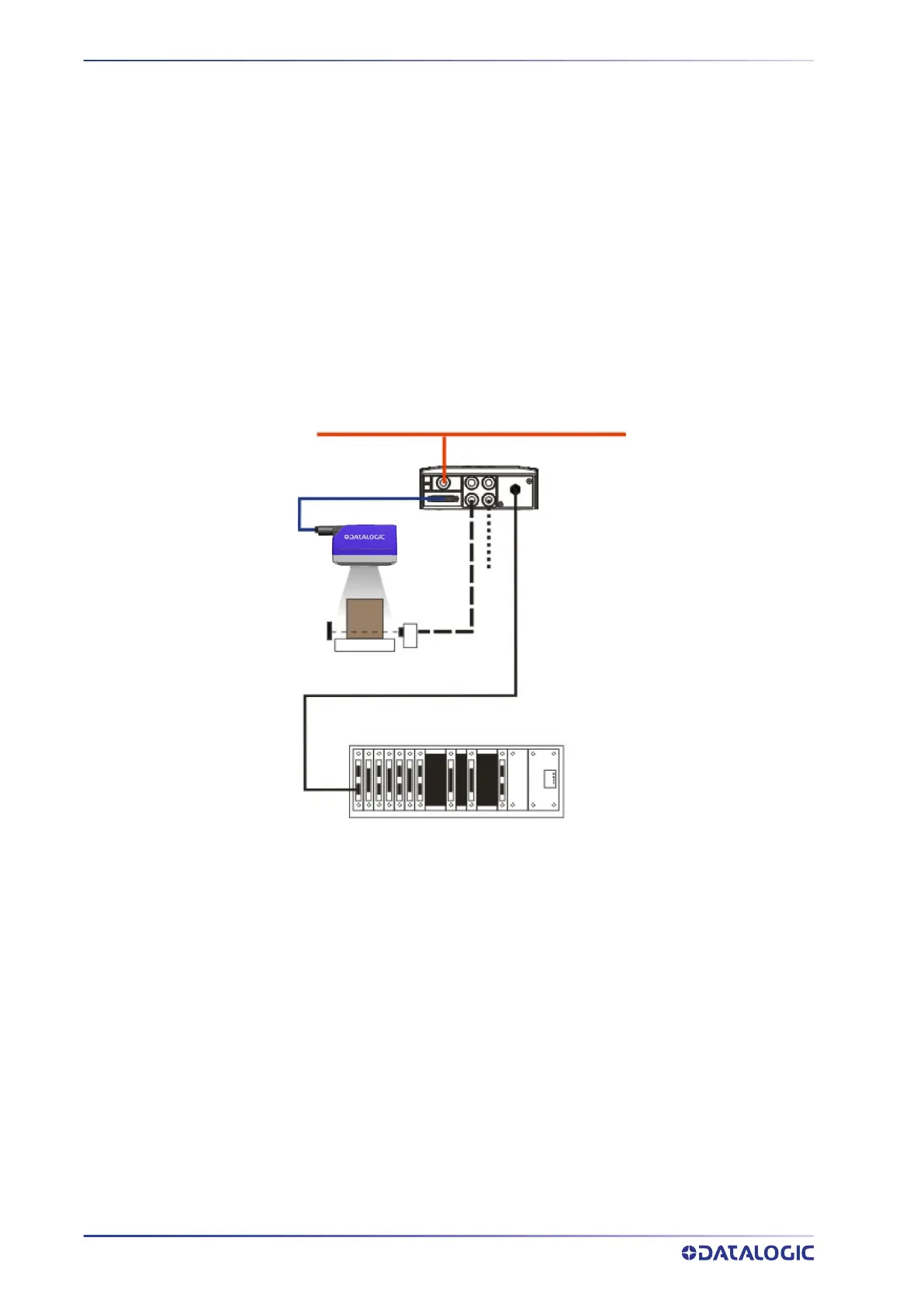
FIELDBUS CONNECTION
In this layout a single reader functions as a Slave node on a Fieldbus network. The data
is transmitted to the Host through an accessory Fieldbus interface board installed inside
the CBX500 connection box.
Reader configuration can be accomplished through the Ethernet interface using the
DL.CODE configuration program.
Data can be transmitted on the RS232 auxiliary interface independently from the Field-
bus interface selection to monitor data.
When One Shot or Phase Mode operating mode is used, the reader can be activated by
an External Trigger (photoelectric sensor) when the object enters its reading zone.
Figure 81 - Fieldbus Interface Point-to-Point Layout
All devices always support multiple output channels (i.e. for data monitoring).
Host
CAB-DSxx-S
Matrix 320
CBX500
Fieldbus Interface (Profibus, DeviceNet, etc.)
Auxiliary Serial Interface (RS232 - Data Monitor)
External Trigger (for One Shot or Phase Mode)
Alone
Power
 Loading...