TYPICAL LAYOUTS
108
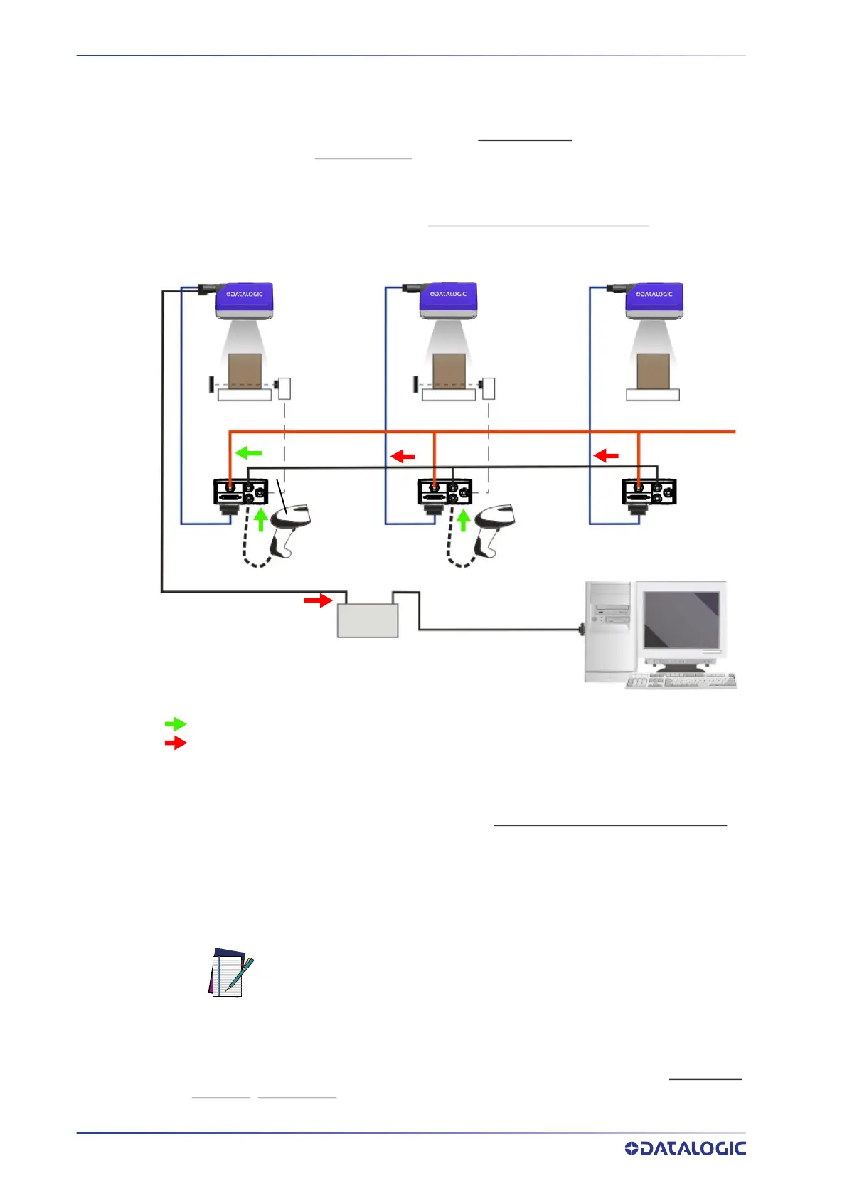
MATRIX 320
ID-NET MULTIDATA NETWORK (PASS-THROUGH)
A special case of the pass-through layout allows each Slave device working Alone, to
collect data from one or more pass-through input channels
and send this data plus its
own on the ID-NET output channel
to the Master.
The Slave readers are connected together using the ID-NET interface. Every Slave reader
must have an ID-NET address in the range 1-31.
The Master collects the data from its pass-through ID-NET input channel
and sends it to
the Host on a different output channel.
Figure 83 - ID-NET Multidata Layout (Pass-through)
In a Pass-through layout each device supports multiple pass-through configurations to
accept input from different devices on different channels (i.e. Master reader above). How-
ever, ID-NET Slave readers are not required to have a pass-through configuration if they
don’t need to receive data from an input channel (i.e. right reader above). The ID-NET
Master always has at least one pass-through configuration to collect the ID-NET Slaves
data and send it to the Host.
All devices always support multiple output channels (i.e. for data monitoring).
In a Pass-through layout each device can have a different operating mode: Continuous
,
One Shot
, Phase Mode, etc.
Host
CAB-DSxx-S
Phase
CAB-ETH-X-M0x
Ethernet TCP/IP Server 1
ID-NET (up to 32 devices, max network extension of 1000 m)
Main Serial Interface (RS232 or RS422 Full-Duplex)
Auxiliary Serial Interface (RS232)
Pass-through Input Channel
Output Channel
Alone
Alone Alone
Switch
Power
Mode
Continuous
Mode
External
Trigger
ID-NET
Master
ID-NET
Slave#1
ID-NET
Slave#2
NOTE
Slave devices cannot receive data from a pass-through ID-NET input
channel and Master devices cannot send data on an ID-NET output chan-
nel.
 Loading...