ALTERNATIVE CONNECTIONS
194
MATRIX 320
INPUTS
There are two opto-coupled polarity insensitive inputs available on the M12 17-pin con-
nector of the reader: Input 1 (External Trigger) and Input 2, a generic input. See "
Inputs"
on page 91
for more details.
The electrical features of both inputs are:
The relative pins on the M12 17-pin connector are:
OUTPUTS
Three general purpose non opto-isolated but short circuit protected outputs are avail-
able on the M12 17-pin connector.
The pinout is the following:
The electrical features of the three outputs are the following:
Reverse-Polarity and Short-Circuit Protected
V
OUT
(I
LOAD
= 0 mA) max = 30 Vdc
V
OUT
(I
LOAD
= 100 mA) max = 3 Vdc
I
LOAD
max = 100 mA
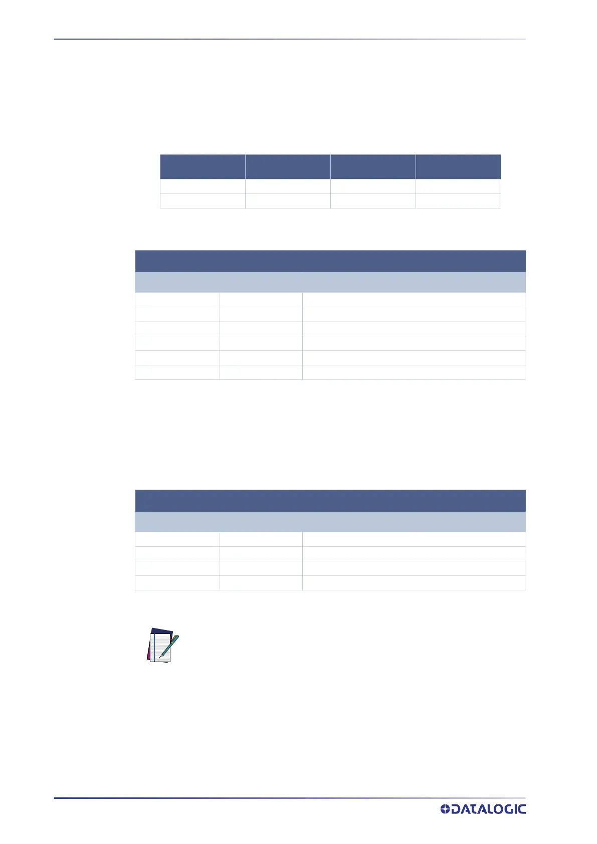
INPUT
| V
AB
| MIN. | V
AB
| MAX. I
IN
MAX
.
Open 0 V 2 V 0 mA
Closed 4.5 V 30 V 10 mA
INPUT PINOUT
PIN NAME DESCRIPTION
1 Vdc Power Supply input voltage +
6 I1A External Trigger A (polarity insensitive)
5 I1B External Trigger B (polarity insensitive)
13 I2A Input 2 A (polarity insensitive)
3 I2B Input 2 B (polarity insensitive)
2 GND Power Supply input voltage -
OUTPUT PINOUT
PIN NAME DESCRIPTION
9 O1 Configurable digital output 1
8 O2 Configurable digital output 2
16 O3 Configurable digital output 3
2 GND Ouptut reference signal
NOTE
Output 1 and Output 2 are opto-coupled when using a CBX.
 Loading...