Home
Datalogic
Barcode Reader
Matrix 320
Datalogic Matrix 320 Product Reference Guide
4
of 1
of 1 rating
220 pages
Give review
Manual
Specs
To Next Page
To Next Page
To Previous Page
To Previous Page
Loading...
174
MATRIX 320
CHAPTER 8
ILLUMINA
T
O
RS
ST
ANDARD ILLUMINA
T
OR
S FOR SOFTW
ARE AD
JUST
ABLE
FOCUS MODELS (LIQUID LENS)
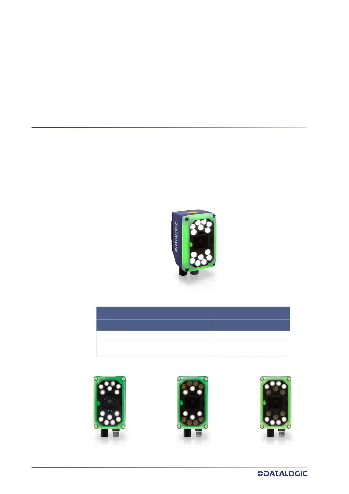
14 LEDs Illuminator
Figure 100
- LED chains for 14 LEDs models
14 LEDs MODELS AND LED CHAIN CONFIGURA
T
ION
LIGHTS ON
LEDs COL
OR
All Chains
White, Red, Blue
Centr
al
Chain
White, Red, Blue
T
op/Bottom Chain
White, Red, Blue
191
193
Table of Contents
Default Chapter
3
Table of Contents
3
Preface
7
About this Manual
7
Manual Conventions
7
Technical Support
7
Support through the Website
7
Reseller Technical Support
8
Compliance
9
General
9
Power Supply
9
EMC Compliance
9
CE Compliance
9
Laser Safety
10
LED Safety
11
Handling
12
General View
14
Matrix 320 (Liquid Lens) with 14 Leds Illuminator
14
Matrix 320 (Liquid Lens) with 36 Leds Illuminator
15
Matrix 320 (C-Mount) Without Illuminator
16
Matrix 320 (C-Mount) with 36 Leds Illuminator
17
Rapid Configuration
19
Matrix 320 with Software Adjustable Focus (Liquid Lens)
19
Step 1A - Connect the System
19
CBX100/CBX500 Pinout for Matrix 320
20
Step 2A - Mount and Position the Reader
21
Step 3A - Aim and Autofocus the Reader
21
Matrix 320 with Manual Adjustable Focus (C-Mount)
23
Step 0B - Assemble the Reader
23
DL.CODE Illuminator Management Procedure
23
Step 1B - Connect the System
23
Step 2B - Mount and Position the Reader
23
Step 3B - Focus the Reader
23
Next Steps for All Models
24
Step 4 - X-PRESS Configuration
24
Aim
24
Setup
24
Learn
25
Restore Reader to Default Environment (Optional)
26
Step 5 - Installing DL.CODE Configuration Program
27
Ethernet Device Discovery
28
Step 6 - Device Configuration
31
Automatic or Advanced Setup
31
Automatic Setup
32
Advanced Setup for Software Adjustable Focus Models (Liquid Lens)
34
Advanced Setup for Manual Adjustable Focus Models (C-Mount)
40
Reading Phase
43
Good Read Setup
44
Data Formatting
45
Output Setup
46
Step 7 - Test Mode
47
Advanced Reader Configuration
48
Host Mode Programming
48
Introduction
49
Product Description
49
Standard Application Program
50
Programmability
50
Excellent Performance
50
Ease of Setup and Use
50
Flexible Solution
51
Connectivity
51
Industrial Strength
51
Indicators and Keypad Button
53
Green/Red Spot and 360° Visual Feedback
54
ID-Net
55
X-PRESS Human Machine Interface
57
X-PRESS Functions
58
Test Mode
58
Aim/Autofocus
59
Setup
59
Learn
59
Diagnostic Indication
60
Model Description
60
Available Models
61
Accessories
61
Matrix 320 C-Mount Assembly
64
Illuminators and Lenses Combinations
65
Application Examples
66
Document Handling
66
Multiple Reading in a Single Image
66
Deformed or Overprinted Code Reading
67
Direct Part Marking
68
Ink-Jet Printing Technology
69
Laser Marking/Etching Technology
69
High Dynamic Range (HDR) Feature
70
Installation
73
Package Contents
73
Mechanical Dimensions
74
Mounting and Positioning Matrix 320
80
Mounting the BK-32-00 Standard Fix Bracket
81
Mounting the BK-32-010 Pivot Fix Bracket
82
Compact Mounting
82
Extended Mounting
83
Matrix 320 C-Mount Mounting Instructions
86
Mounting Instructions for Matrix 320 C-Mount Without Illuminator
86
Mounting Instructions for Matrix 320 with 36 LED Illuminator
88
Heat Sink Mounting Instructions
90
When to Mount the Heat Sink
90
How to Mount the Heat Sink
90
Accessory Covers and Filters
92
Covers
92
Standard and ESD Covers
92
Polarizing Covers
92
Cover Replacement
93
Filters
95
Filter Mounting Instructions
95
Cbx Electrical Connections
97
CBX Connection Box Pinout
98
CAB-Ds0X-S Pinout
99
Power Supply
100
Main Serial Interface
101
RS232 Interface
101
RS422 Full Duplex Interface
102
ID-NET Interface
103
ID-NET Cables
103
ID-NET Response Time
104
ID-NET Network Termination
105
ID-NET Connection Diagrams
105
Auxiliary RS232 Interface
108
Inputs
109
External Trigger Input Connections Using Matrix 320 Power
110
External Trigger Input Connections Using External Power
112
Input 2 Connections Using Matrix 320 Power
113
Input 2 Connections Using External Power
114
Input 3 Connections (CBX500 Only)
114
Outputs
115
Output 1 and 2 Connections Using Matrix 320 Power
116
Output 1 and 2 Connections Using External Power
117
Output 3 Connections Using Matrix 320 Power (CBX500 Only)
118
Output 3 Connections Using External Power (CBX500 Only)
118
On-Board Ethernet Interface
119
User Interface - Serial Host
119
Typical Layouts
120
Ethernet Connection
121
Serial Connection
123
Fieldbus Connection
124
Pass-Through
125
ID-NET Multidata Network (Pass-Through)
126
ID-NET Synchronized Network
127
Reading Features
128
FOV Calculation
128
Global FOV Diagrams
129
Global FOV for Matrix 320 LQL-9
130
Global FOV for Matrix 320 LQL-16
131
Global FOV for Matrix 320 C-Mount LNS-4
132
Global FOV for Matrix 320 C-Mount LNS-6
133
Global FOV for Matrix 320 C-Mount LNS-8
134
Global FOV for Matrix 320 C-Mount LNS-12
135
Global FOV for Matrix 320 C-Mount LNS-16
136
Global FOV for Matrix 320 C-Mount LNS-25
137
Global FOV for Matrix 320 C-Mount LNS-35
138
Maximum Line Speed and Exposure Time Calculations
139
Software Configuration
141
DL.CODE System Requirements
141
Reader Configuration
142
Auto-Calibration
143
Manual Calibration
144
Under-Exposure
144
Over-Exposure
145
Moving Code out of the Field of View
146
Multi Image Acquisition Settings
147
Automatic Image Settings Selection
148
External Image Settings Selection
149
Extending DOF with Automatic Image Settings Selection (Cycle All in same Phase) for Liquid Lens Models
151
Extending DOF with Automatic Image Settings Selection Sequence (Input Select) for Liquid Lens Models
152
Image Cropping
154
Direct Part Marking Applications
156
Image Filter
157
Pass-Through Configurations
161
Internal Network Configurations
163
Master Configuration
164
Multidata ID-NET Network Configurations
166
Synchronized ID-NET Network Configurations
171
Verify Master/Slave Synchronized Configuration
175
Backup and Restore through DL.CODE
178
Backup
179
Restore
180
Replacement
180
Restore Defaults
181
Restore Default Environment
181
Restore Default Startup Configuration
182
Restore Factory Defaults
182
Diagnostic Alarms
183
Statistics
184
BM150 Display Module Configuration and Messages
185
Configuration through DL.CODE
185
Accessing the HMI Interface through Keypad and Display Menu
186
Display Messages
188
BM150 Backup and Restore Procedure
191
Illuminators
192
Standard Illuminators for Software Adjustable Focus Models (Liquid Lens)
192
14 Leds Illuminator
192
Leds Illuminator
193
Standard Illuminators for Manual Adjustable Focus Models (C-Mount)
194
36 Leds Illuminator
194
Polarizer
195
Direct Part Marking Applications
198
Matrix 320 Recommended Illumination
199
Color Contrast Considerations
200
Maintenance
202
Cleaning
202
Troubleshooting
203
General Guidelines
203
Technical Features
206
Alternative Connections
210
Power, Com and I/O Connector for Standard Models
210
On-Board Ethernet Connector
211
ID-NET Network Termination
211
Inputs
212
Outputs
212
User Interface - Serial Host
214
Glossary
215
Other manuals for Datalogic Matrix 320
Quick Start Guide
2 pages
4
Based on 1 rating
Ask a question
Give review
Questions and Answers:
Need help?
Do you have a question about the Datalogic Matrix 320 and is the answer not in the manual?
Ask a question
Datalogic Matrix 320 Specifications
General
Brand
Datalogic
Model
Matrix 320
Category
Barcode Reader
Language
English
Related product manuals
Datalogic Matrix 300
160 pages
Datalogic Matrix 300N
248 pages
Datalogic Matrix 210
142 pages
Datalogic Matrix 220
212 pages
Datalogic Matrix-2000
11 pages
Compact 2D Reader Matrix-2000
108 pages
Datalogic Magellan 83
17 pages
Datalogic MAGELLAN 8400
17 pages
Datalogic Magellan 800i
184 pages
Datalogic Magellan 9300i
520 pages
Datalogic Magellan 1100i
2 pages
Datalogic Magellan 2200VS
432 pages