GLOBAL FOV DIAGRAMS
PRODUCT REFERENCE GUIDE
111
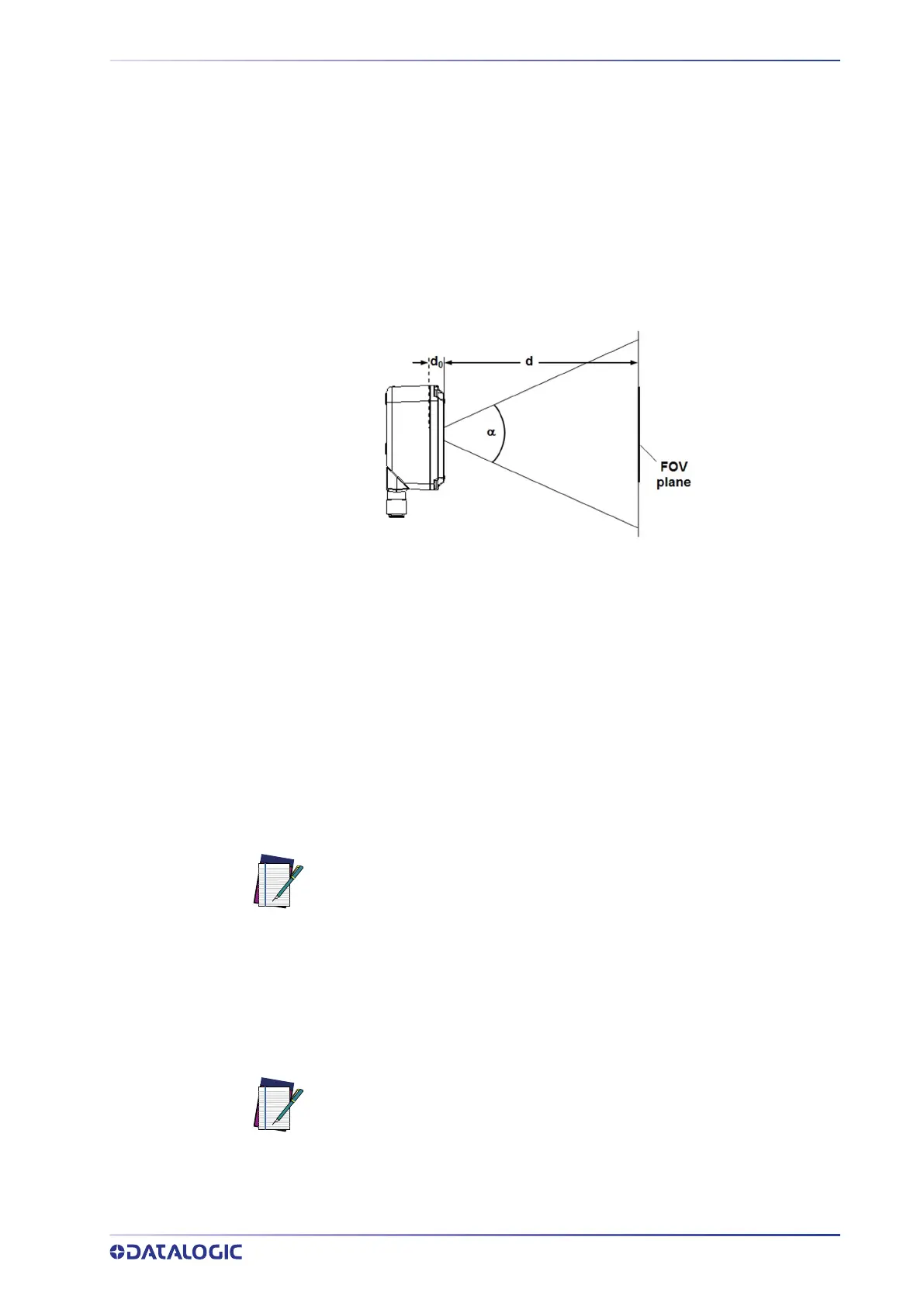
The viewing angle has a tolerance of ± 1° depending on the reading distance.
FOV
x
= 2 [ (d + d
0
)
*
tan (α
x
/2) ]
where:
FOV
x
= horizontal, vertical or diagonal FOV
x
= horizontal, vertical or diagonal viewing angles.
d = reading distance (in mm) from window surface to code surface
d
0
= offset (in mm) from center of lens to external window surface
Figure 85 - Reading Distance References
Example:
The FOV for a Matrix 320 7xx-330 at a reading distance of 600 mm is:
FOV
H
= 2 [(600 mm + 22 mm) * tan (34°/2)] 380 mm
FOV
V
= 2 [(600 mm + 22 mm) * tan (19°/2)] 208 mm
GLOBAL FOV DIAGRAMS
The following diagrams show the maximum obtainable Field of View for 1D and 2D
codes. Depending on the code resolution, symbology, and number of characters in the
code, the Reading Area can be different from the FOV.
NOTE
The following diagrams are given for typical performance at 25°C using
high quality grade A symbols according to ISO/IEC 15416 (1D code) and
ISO/IEC 15415 (2D code) print quality test specifications. Testing should
be performed with actual application codes in order to maximize the
application performance.
NOTE
The following diagrams refer to Matrix 320 with 14 LEDs illuminator.
For Matrix 320 with 36 LEDs illuminator, the reference distances from
the exit window should be reduced by 15 mm (internal offset difference
between 14 LEDs and 36 LEDs models).
 Loading...