BM150 DISPLAY MODULE CONFIGURATION AND MESSAGES
PRODUCT REFERENCE GUIDE
171
Diagnostic Alarms
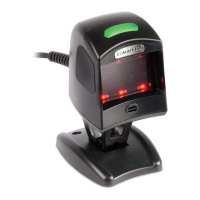
Diagnostic error messages are sent to the BM150 display as numeric Alarm Codes (even
if Failure Messages are selected for data transmission the numeric Alarm Code is sent to
the display).
X = numeric Alarm Code (see below for the list of Alarm Codes)
R = Device Network Type – MUL=Multidata, SYN=Synchronized, ALN=Alone
N = Device Network Setting – M00=ID-NET Network Master, Sxx= ID-NET Network Slave
address, Null string= Alone (no network)
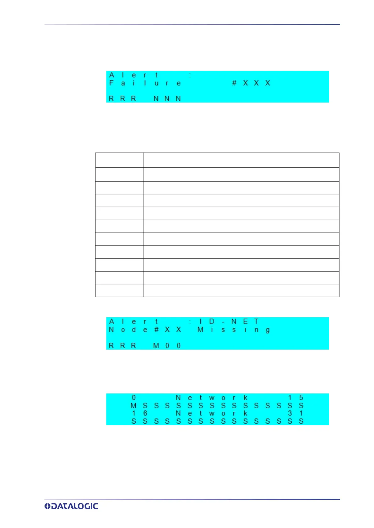
Slave Node Alarms (Master only)
X = slave node number (1-31)
R = Device Network Type – MUL=Multidata, SYN=Synchronized
Network State (Master only)
M = Master diagnostic condition; S = Slave diagnostic condition:
* = scanner OK
- =scanner not detected at startup
? =scanner detected at startup but not responding to diagnostic polling
! = scanner diagnostic error
Alarm Code Description
1 Slave No Reply
64 Slave Address Duplication
171 Protocol Index Failure
185 Backup Memory Communication Failure
187 Wrong Rotary Switch Selection
189 Fieldbus Communication Failure
191 Fieldbus Type Mismatch
193 Fieldbus Configuration Error
195 Fieldbus DHCP Problem
201 No XRF Slave(s) Detected
 Loading...