AUSTROMAT
®
664 iSiC
®
/ 674 baSiC
2
3. Design and functionalit
Operating Instructions (Version 03/2018) 23
3. Design and functionality
3.1. Front of system
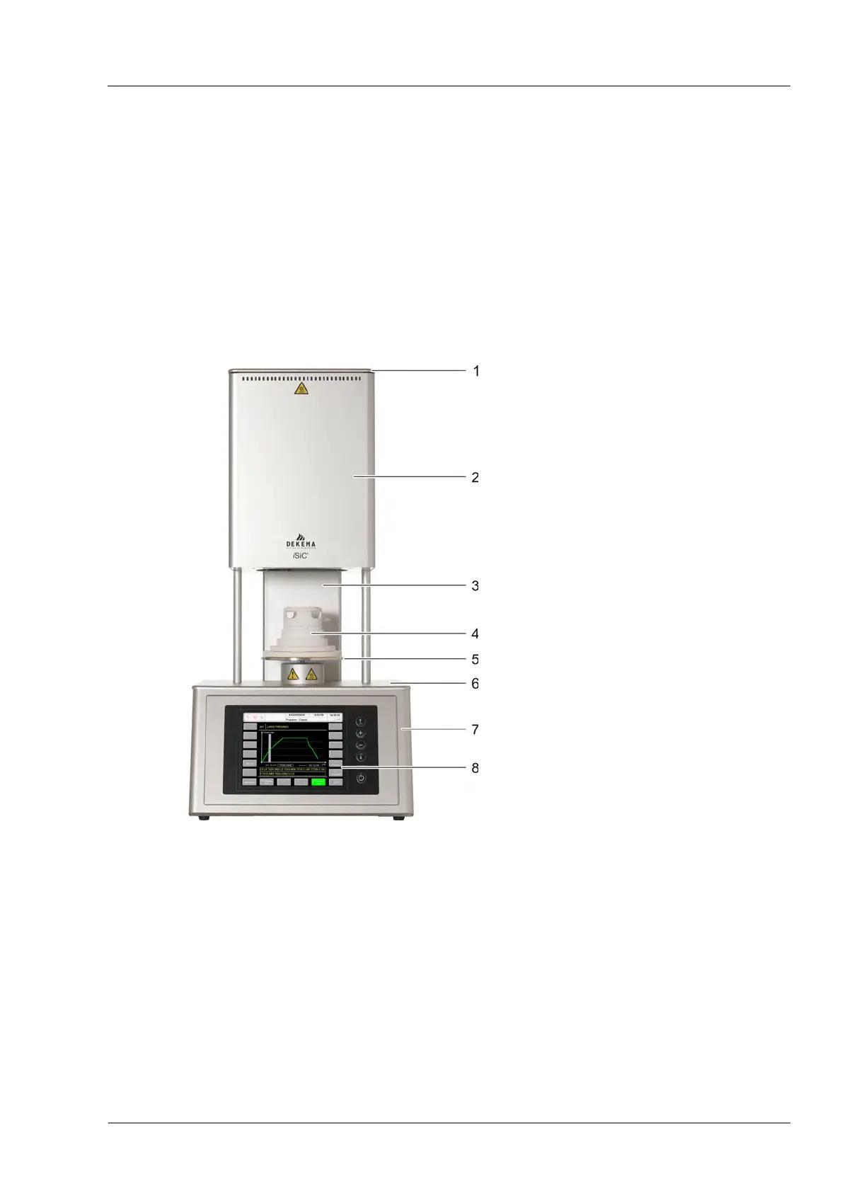
The following figure shows the front of the AUSTROMAT
®
firing furnace and identifies the most
important components.
Fig. 3-1 Front view of the firing furnace (example AUSTROMAT
®
664)
1 Firing chamber cover 5 Lift seat with sealing ring
2 Top of furnace with firing chamber 6 Bottom cover plate
3 Back column 7 Bottom oven part with electronics
4 Insulation table 8 User interface with touchscreen
The top of the firing furnace contains the firing chamber. The firing chamber cover contains
ventilation slots for cooling the firing furnace. The area in the bottom of the housing contains the
electronic and mechanical furnace components. used to move the lift system comprising the lift
rod, lift seat with sealing ring (O-ring), and the insulation table on which the objects to be fired
are placed. The firing furnace is operated using a touchscreen and function keys.