3. Design and functionality AUSTROMAT
®
664 iSiC
®
/ 674 baSiC
2
26 Operating Instructions (Version 03/2018)
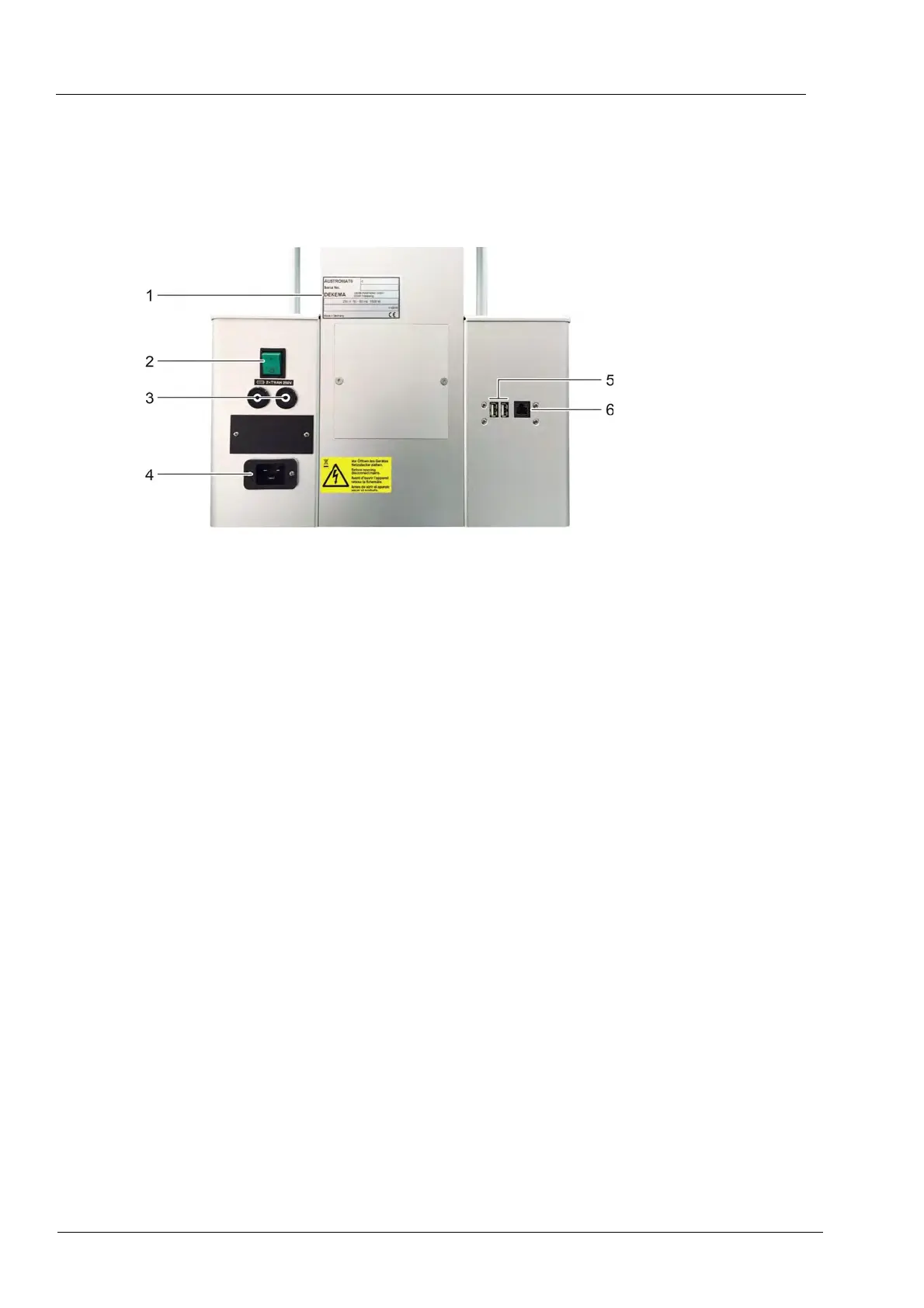
3.3. Rear of device
The following figure shows the back of the bottom part of the AUSTROMAT
®
firing furnace and
identifies the most important components.
Fig. 3-3 Rear view of the firing furnace (example)
1 Rating plate with serial number 4 Connection socket for the power cable
2 Main switch 5 USB interface
3 Fuse holder with fuses 6 Network interface (optional)
The standard equipment on the back of the device comprises:
• The main switch for turning the device on and off,
• Two fuse holders with integrated fuses (see section 1.5),
• Con
nection socket for the power cable,
• Two interfaces:
• USB interface for connecting a USB device such as a USB stick, USB keyboard or
USB mouse,
• Optional network interface for connecting an Ethernet cable (connecting the firing
furnace to a network), or a crossed network cable (connecting the firing furnace to an
individual computer).