5 Applied Instructions and Basic Usage
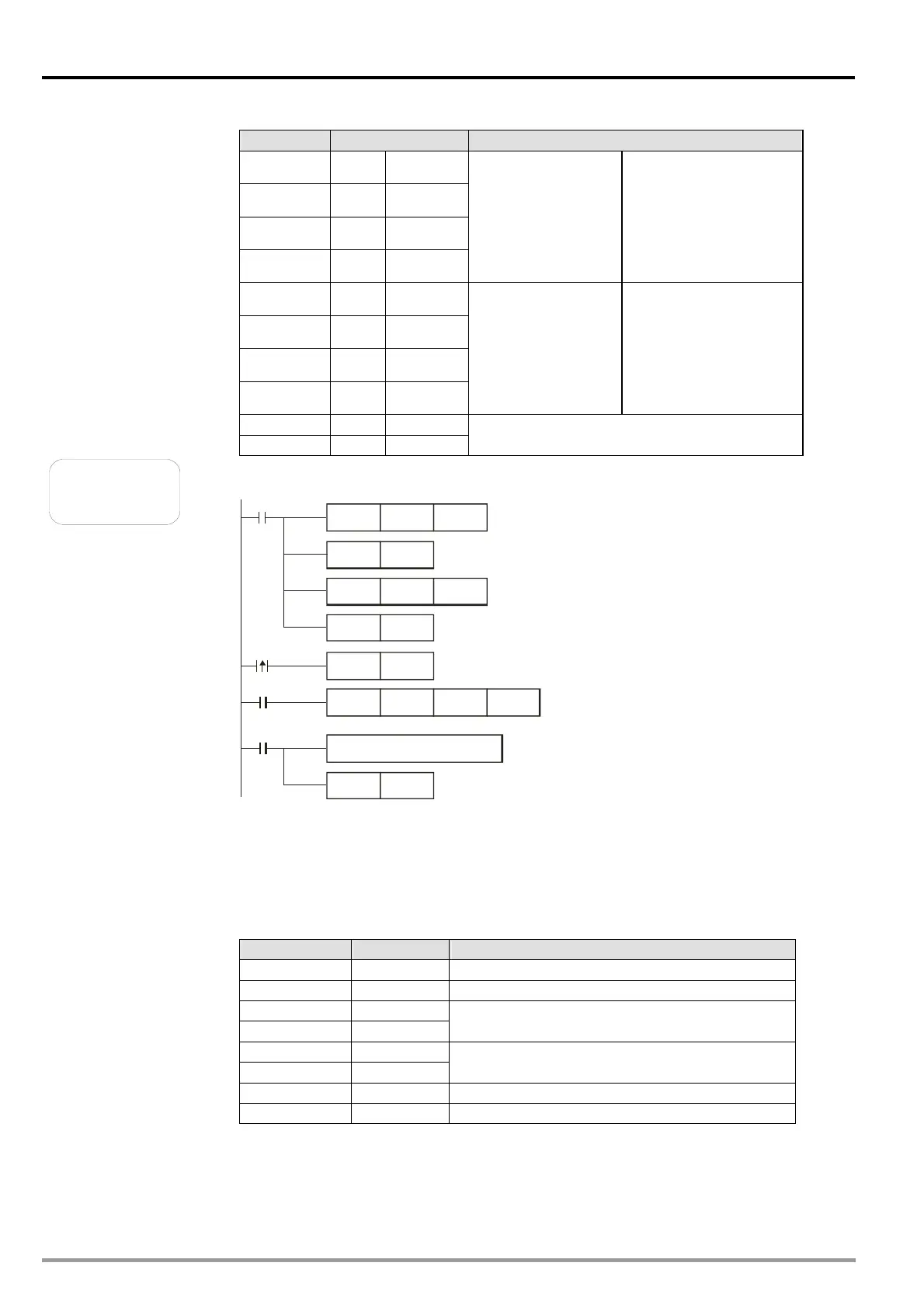
Register Data Description
D1081 low ‘0’ 30 H
D1081 high ‘1’ 31 H
D1082 low ‘3’ 33 H
D1082 high ‘6’ 36 H
Contents of the
address 2105 H
The DVP-10PM series
motion controller
automatically converts
the ASCII characters
into values, and store
the values in D1054.
(D1054=0136 H)
D1083 low ‘0’ 30 H
D1083 high ‘0’ 30 H
D1084 low ‘0’ 30 H
D1084 high ‘0’ 30 H
Contents of the
address 2106 H
The DVP-10PM series
motion controller
automatically converts
the ASCII characters
into values, and store
the values in D1055.
(D1055=0000 H)
D1085 low ‘3’ 33 H LRC CHK 1
D1085 high ‘B’ 42 H LRC CHK 0
Example 2
A DVP-10PM series motion controller is connected to a VFD-B series AC
motor drive (RTU mode: M1143=ON)
Processing the data received
Communication protocol: 9600,8,E,1
The communication protocol set is retained.
Communication timeout: 100 ms
M1127 is reset.
Request for sending data
The data received is stored in D1070~D1085 in the form
of hexadecimal values.
Communication command:
Device address: 01
Data address: H2102
Data length: 2 words
The reception
of data is complete.
M100
MOV
H87 D1120
SET M1120
MOV
K100
D1129
RST
M1127
M1127
SET M1122
X0
X0
MODRD
K1
H2102
K2
SET
M1143 RTU mode
DVP-10PM series motion controller VFD-B series AC motor drive: The
DVP-10PM series motion controller sends “01 03 2102 0002 6F F7”.
VFD-B series AC motor drive DVP-10PM series motion controller: The
DVP-10PM series motion controller receives “01 03 04 1770 0000 FE 5C”.
Data transmission registers in the DVP-10PM series motion controller
(message sent by the DVP-20PM series motion controller):
Register Data Description
D1089 low 01 H Address
D1090 low 03 H Function
D1091 low 21 H
D1092 low 02 H
Starting data address
D1093 low 00 H
D1094 low 02 H
Quantity of Data (count by the word)
D1095 low 6F H CRC CHK Low
D1096 low F7 H CRC CHK High
DVP-20PM Application Manual
5-88

 Loading...


