11 CANopen Communication Card
CR#n50: SDO access command and status
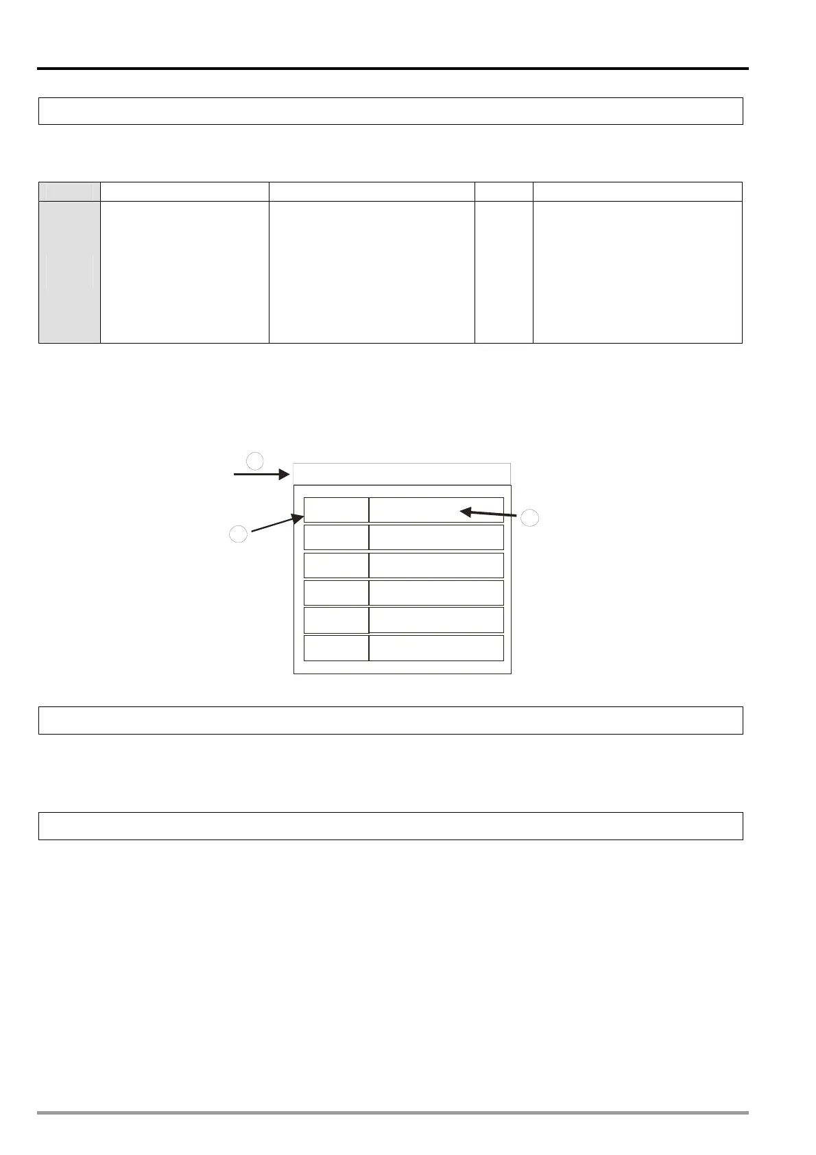
[Description]
The control register is used to set an SDO access command, and obtain a status. Please refer to the
table below for more information.
Bit
Bit [15:8] Bit [7:4] Bit [3] Bit [2:0]
Setting
value
Subindex of a target OD
index
Data length (Unit: Byte)
Range: 1~8
If users want to write data, they
have to specify a data length.
Error
flag
Command:
0: Completed
1: Writing (including a check)
2: Reading (including a check)
3: Writing (not including a
check)
4: Reading (not including a
check)
Example: SDO data transmission
1. Specify the OD index of an SDO server in CR#n51.
2. Set the data to be transmitted in CR#n52~CR#n55.
3. Refer to the table above. Specify a subindex in bit 15~bit 8 in CR#n50, and an SDO access
command.
OD index
Subindex
Data
Data
Data
Data
Data
Data
1
3
2
Subindex
Subindex
Subindex
Subindex
Subindex
CR#n51: SDO OD (object dictionary) index
[Description]
The control register is used to specify the OD index of a node.
Range: H’0000~H’FFFF.
CR#n52~CR#n55: SDO transmission/reception register 1~SDO transmission/reception register 4
[Description]
The data to be accessed through an SDO protocol is stored in the four control registers. The maximum
capacity is 1024 bytes. If an error occurs during SDO data transmission, an error code will be stored in
CR#n52 and CR#n53. If CR#n52~CR#n55 are used at a time, CR#n52 functions as the LSB and
CR#n55 functions as the MSB.
DVP-20PM Application Manual
11-12

 Loading...


