12-4.3 Settings
Amp: Equal to the measured signal amplitude transmitted by DS2831. It must comply with
network management requirements. (It is recommended to limit the transmitted signal
amplitude as much as possible to avoid interference with other comms, DTV or DOCSIS
signals in the network, increase overall RF power, and/or generating distortion products.)
Input range: 0~60 dBmV
Time step: Equal to the transmission delay between two adjacent frequency points. Input range:
10ms ~ 30s
Freq: This signal is bursty and at a single frequency.
Do not
use occupied spectrum when
setting up, this is an interfering signal carrier. Input range: 42~120 MHz
12-5 System Connection
12-5.1 Headend System Connection
1.
The DS1610-1D connects with your upstream optical receiver test points (the same as your CMTS)
2.
The DS1615 output signal is combined into downstream optical transmitter signal. (DC coupler
connection)
Note: Before combining the signal with your downstream broadcast network,
be sure to verify
that the
chosen DS frequency is unused by any other live signals.
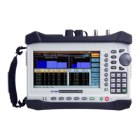
12-5.2 DS2831 Connection
1.
The DS2831 has two ports: RF and COM. The RF port is the receiver port for local position spectrum
signals. Press
R-Sweep
>
Com
>
RF
to enable the RF port to receive the comms signals. The COM port is
for upstream transmission being generated by the DS2831 towards the DS1610 system upstream, used in
bidirectional measurements. By default, the COM port receives the FSK communication signal.
2.
At terminal position, if you want to look at all the information, use a two-way splitter, one splitter's path
connected to the COM port, to transmit upstream test signals and receive the DS1610 broadcast signal,
another path connected to RF port to measure local position spectrum traces.
At the optical node or bidirectional amplifier, the COM port of the DS2831 should be connected to the
bi-directional amplifier (or bidirectional optical node) reverse path output test port; the RF port should
be connected to the output test port of a bi-directional amplifier (or bi-directional optical node).
12-6 Troubleshooting
If the DS2831 cannot register, use the spectrum analysis function of the DS2831 to verify whether the
downstream signal sent by DS1615 is active & normal or not. If not, check the relevant parameter settings of
the downstream communication and health of the downstream network; then run the client side of the
DS1610-1D. Open the 1610-1D port connected with the DS2831, and open the maximum value display.
When the DS2831 is registering, the frame should pause for a while, and the maximum value should show
that the "pilot frequency" has a signal which is over the "pilot amplitude"; if it doesn’t display or the
amplitude value is lower, verify the relevant parameter settings of the upstream comms channel and the
status of the upstream network.