7-4 Chrominance to Luminance Delay Inequality
Chrominance and luminance are measured together with the 12.5T test signal. The Chrominance to
Luminance Delay measurement is required by the FCC because a large delay displaces the color vs
luminance, degrading the edges in the picture. Error in gain, meanwhile, merely changes color saturation.
The 12.5T signal is the sum of a low frequency pulse (also sine
2
) and a burst of color sub-carrier modulated
with an envelope that is exactly the same as the low frequency pulse. The burst is then shifted up such that
the bottom is now flat. Gain or delay errors will distort the flat bottom. Gain smaller than 1 forces the bottom
up, while gain larger than 1 lowers it. Chroma delay creates an “S” shape on the bottom, which is inverted
when the delay is negative. The analysis of the 12.5T is a measurement of the normalized distortion of that
bottom: ratio and peak-to-peak values of the peak and valley.
When the test signal was first developed, engineers used charts to visually calculate Y to C delay and gain.
Now, automated measurements perform the same task by analyzing the envelope of the signal.
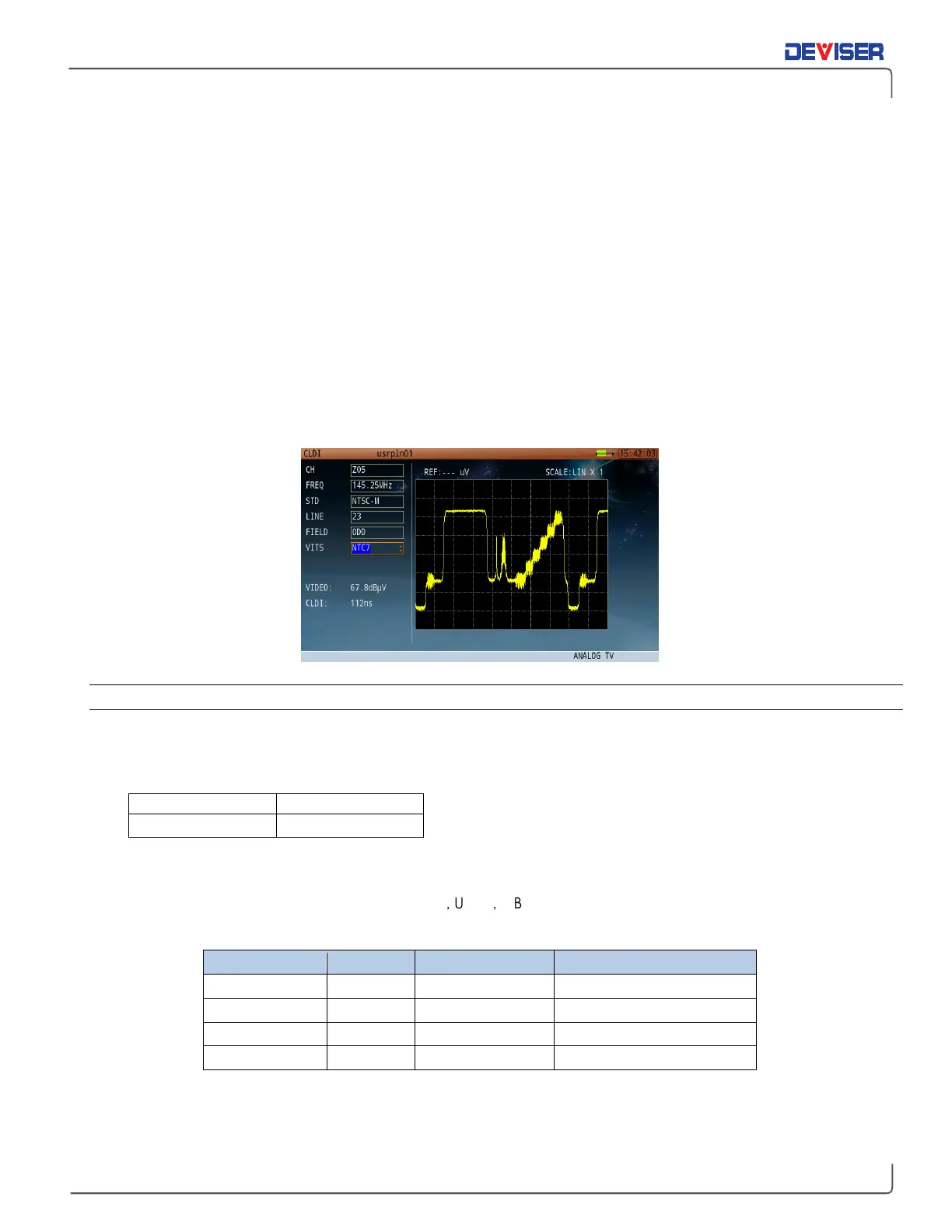
For analog TV channels, press
CLDI
to enter the Chrominance-Luminance Delay Inequality menu.
7-4.1 Settings
The DG/DP function allows you to change the following settings. Possible values are listed when applicable.
Chrominance pulse values required for various combination test signals:
VITS signal:
For per frame 525 lines system, VITS signal: FCC and NTC-7
For per frame 625 lines system, VITS signal: CCIR17
,
UK ITS
,
GB19
(Detailed VITS signal information is documented in Section 25-3 of this User Guide.)
TV standard Line/Frame
Field frequency Color encoding technique
NTSC-M 525 60Hz NTSC
PAL-M 525 60Hz NTSC
PAL-B,D,G,H,I,K 625 50Hz PAL
PAL-N 625 50Hz PAL
Per frame 525 lines system: Field 1 (odd field), line 1-263; Field 2 (even field), line2-262
Per frame 625 lines system: Field 1 (odd field), line 1-313; Field 2 (even field), line2- 312