Part II: Settings and Measurements
Chapter 24: Optical Fiber Applications
The DS2831 is equipped with a variety of optical measurement functions and tools, for use in testing and
maintenance of fiber-optic communications equipment. These include:
•
Optical power meter (OPM)
•
Visual fault locator (VFL)
•
Fiber optical inspection scope (FIP)
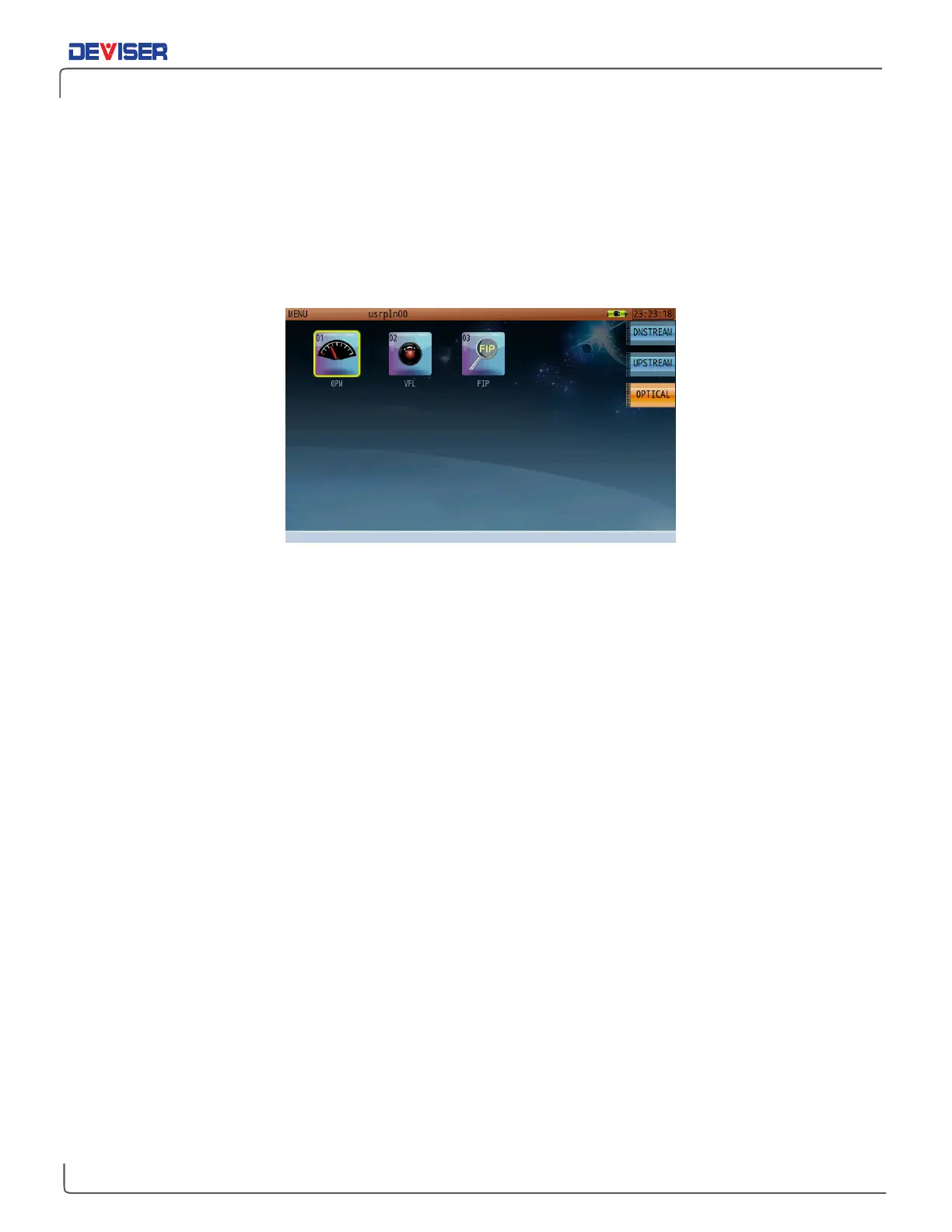
Optical Measurement Screen
From the
Home
menu, press F3 to open the optical measurement menu (shown above). The optical power
meter (OPM), visual fault locator (VFL) and fiber optical inspection scope (FIP) applications are available
from this screen; use the rotary knob or dial the appropriate icon number to launch your desired function.
24-1 Introduction to Fiber Connectors
Fiber connectors are the most common passive device used in the field of fiber-optic communications.
These components connect the endfaces of two optical fibers, allowing the continuous transmission of
optical signal. In an optical communications system, connectors appear at nearly every juncture: fiber end-
faces, passive and active optical components’ input and output ports, fiber jumpers, and more.
An optical fiber connector is composed of a pin and connector. For example, with the FC/PC connector
type, “FC” specifies one of several external connection types. (Other external connection formats include
SC, ST, LC, MU, MT-RJ, D4, and E2000.) “PC” indicates the shape of the pin (or “endface”), which can be of
the PC, APC, or UPC standards.
Let’s take a closer look at these different types of fiber endface.