Part III: Background and Concepts
Chapter 28: Detector Mode
When measuring and analyzing different types of signals with a spectrum analyzer, the detector mode
should be set correctly. “Pixel point” is an important concept related to the detector mode of a spectrum
analyzer. Suppose the spectrum curve is divided into “n” pixel points. When the span of the spectrum is
large, each pixel point contains a relatively large frequency range of information (acquired data or
acquisitions).
Screen size and resolution limits the amount of pixels that can be displayed on the screen, and since each
pixel point can only show one value, each pixel may represent multiple measurement (or sample or
acquisition) points. It is clear that not all data points can be displayed on the screen of a small portable
piece of equipment so each displayed pixel on the screen must be processed to reduce the number of
displayed pixels.
Detector modes & applications
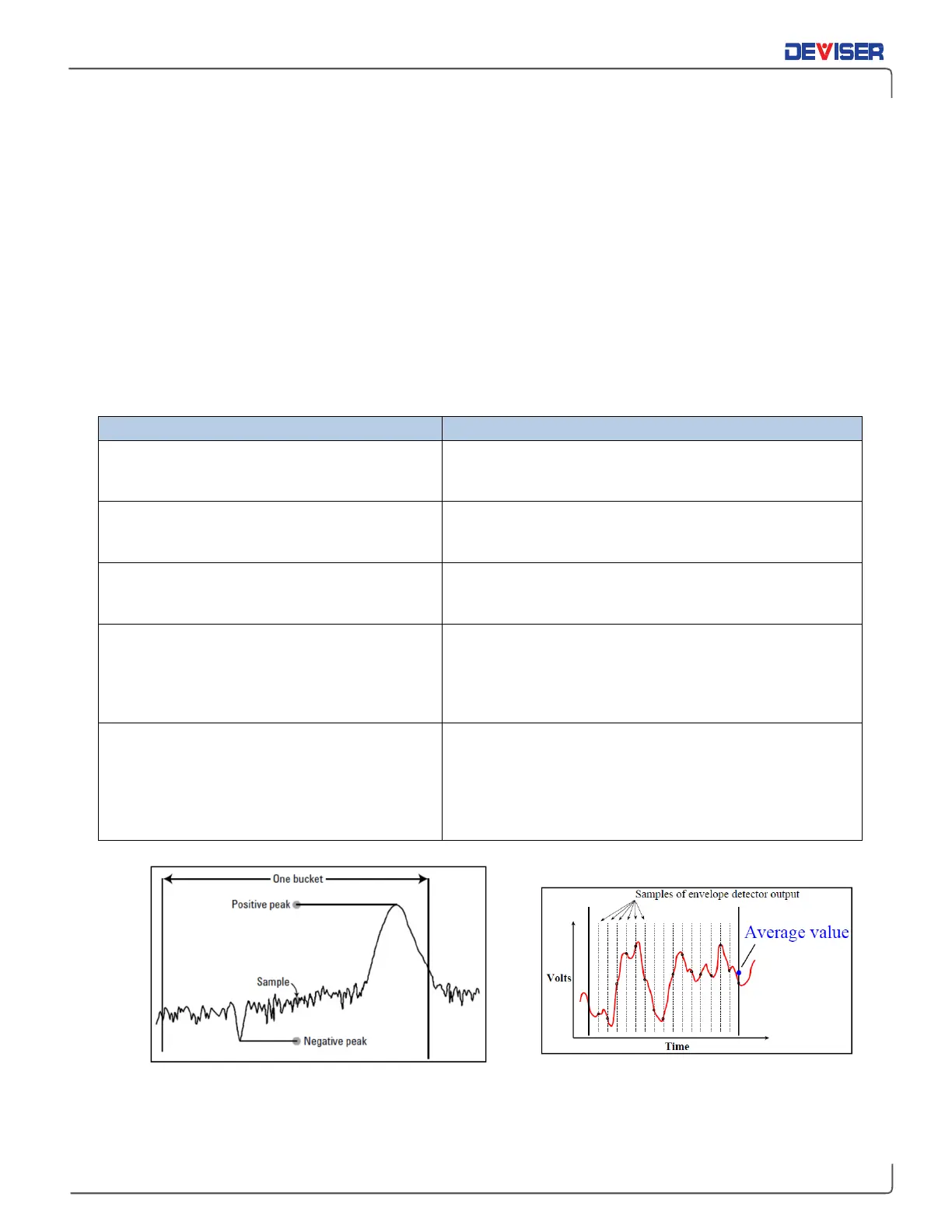
Positive peak detection
CW signal and peak signal level measurements.
Effective for detecting the maximum value from all
sample points of a pixel point to display.
Sample detection
Noise signal measurements. Randomly selects a
sample point from all acquisitions (or sample) points. It
represents random noise fluctuations very well.
Negative peak detection
resolution signal measurements. Effective for
detecting the minimum value from all sample points
of a pixel point to display.
Average detection
ACPR and channel power measurements. Each pixel
point represents multiple sample points & amplitude
data. Average detection uses each sample point’s
data for each pixel point, averaging the linear value
of all sample points dedicated to each pixel point.
RMS (Root-Mean-Square) detection
Total power measurements or noise
CDMA, QAM). Calculates value of all sample points
allocated to each pixel point; the result corresponds
to the signal power in the selected bandwidth. In RMS
detection mode, it is recommended that the VBW
filter be ≥3 times the RBW filter.
The number of trace points saved in memory is based on detector algorithm Principle of Average Detector