5-8 Tilt Measurement
The Tilt measurement helps to quickly measure the flatness of a CATV system and the gain of the splitters /
taps. This feature provides power levels for up to 16 channels. Upon entering the Tilt function, you will be
prompted to set the tilt channel plan. A minimum of 4 channels is required to begin measuring.
There are 2 markers in the tilt measurement screen. Press
Mark A
(F3) to activate MarkerA on the screen;
press F3 again to activate
Mark B
. You may only control the marker that’s currently active. When you move
the marker over a channel using the arrow keys, its level and channel type are displayed.
The Tilt measurement has two different view modes:
Graph
and
List
. Press F1 to toggle between them.
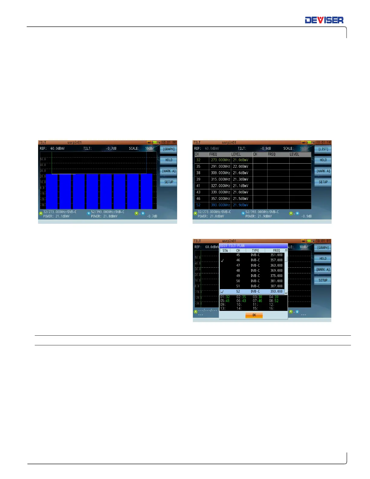
Tilt Measurement – Graph Display Tilt Measurement – Channel Listing Display
You can select the channels in your tilt plan from the
tilt editing dialog (shown right). Choose 4-16 channels
from the list of active channels in the active channel
plan to perform a tilt measurement.
All active channels in the channel plan are listed and
available in the tilt plan editing dialog.
5-8.1 Settings
Button Operation
[Graph] / [List]: Toggles the measurement display between Graph and List mode.
Hold: Pauses the measurement. Press again to resume.
[MarkA] / [MarkB]: Toggles the active marker between A and B.
Setup: Opens the tilt plan editing dialog, allowing you to select 4-16 channels to test.
Test Results
In Graph mode, all selected channels – no matter which – are automatically organized by frequency from
left to right. The tilt value (“A-B”) is measured between Markers A & B.
Analog channels measure the peak sync pulse of the video carrier, while digital channels measure average
power.