Part II: Settings and Measurements
8-7
Adaptive Equalizer, Frequency Response, and Group Delay
A digital equalizer is an adaptive filter that "optimizes" the received signal – in this case, a MER signal –
before demodulation. Equalizers were originally used to minimize inter-symbol interference, the residual
effects of one symbol on its neighbors as caused by filters in the communication channel and reflections.
Digital equalizers are filters whose amplitude and phase responses are the inverse of the communication
channel’s, such that the overall response restores the original signal.
Although impairments may be linear or non-linear, digital adaptive equalization will compensate only for
linear distortions. These are caused by the distortion of the signal by the transmission channel. Examples
include frequency response, group delay, micro-reflections, phase noise, etc. These distortions qualify as
linear distortions as they apply linearly, or equally, to the whole signal. Non-linear impairments don’t apply
equally to all symbols.
Equalizer filters add a little of the values of all the other stages to the main tap. The filter is adaptive, so it
adjusts the multiplying coefficient of the stages in order to optimize the MER. The mechanism of control
slightly modifies the coefficients for each stage in order to decide if the modification improves or degrades
the MER. If the complex coefficients of the filter are known, it is possible to calculate the power contribution
from each stage. So each stage’s power contribution corresponds to the power of correction of the linear
distortion. The nonlinear power of distortion (obtained from MER after equalization) added to the linear
power of distortion (obtained from equalizer coefficients) gives us a total power of distortion corresponding
to an MER without equalization.
Why expend so much effort for such a small difference? Even a very small improvement in MER is sufficient
to reduce the error rate (BER) by several orders of magnitude.
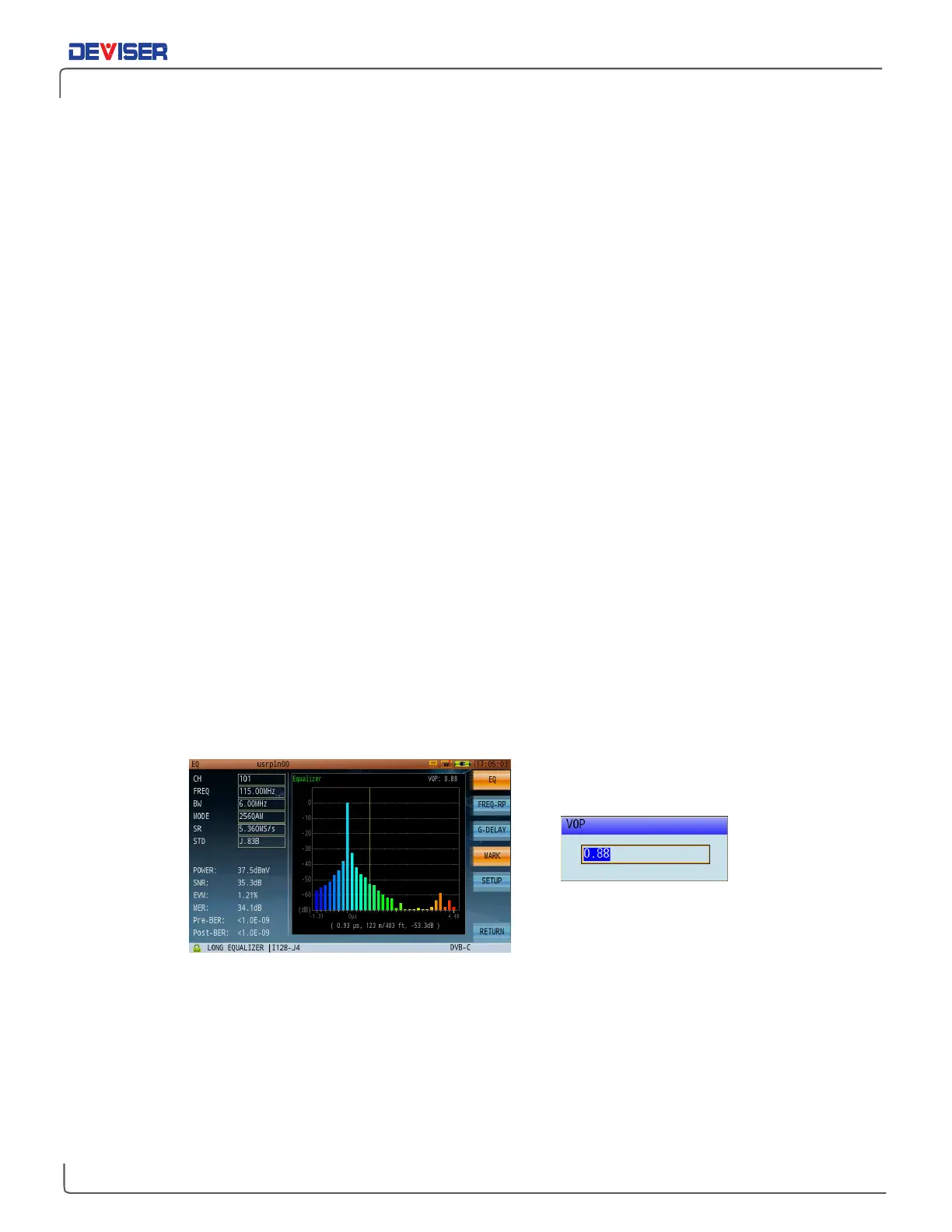
Another benefit of the digital adaptive equalizer is its ability to use reflections (impedance mismatch) to
help determine the location of faults. When you turn the rotary knob on the equalizer display interface,
moving the marker on different tap, the bottom of the graph displays additional details such as time (of the
selected tap away from the main tap); distance (feet or meters); and the relative amplitude level of that
tap. When looking for reflections, you can see in the adaptive EQ graph that one or several taps exceed
the amplitude of all the others. Move the marker to that tap position to measure an approximate distance
to the fault.
Adaptive Equalizer Analysis Velocity of Propagation