Part II: Settings and Measurements
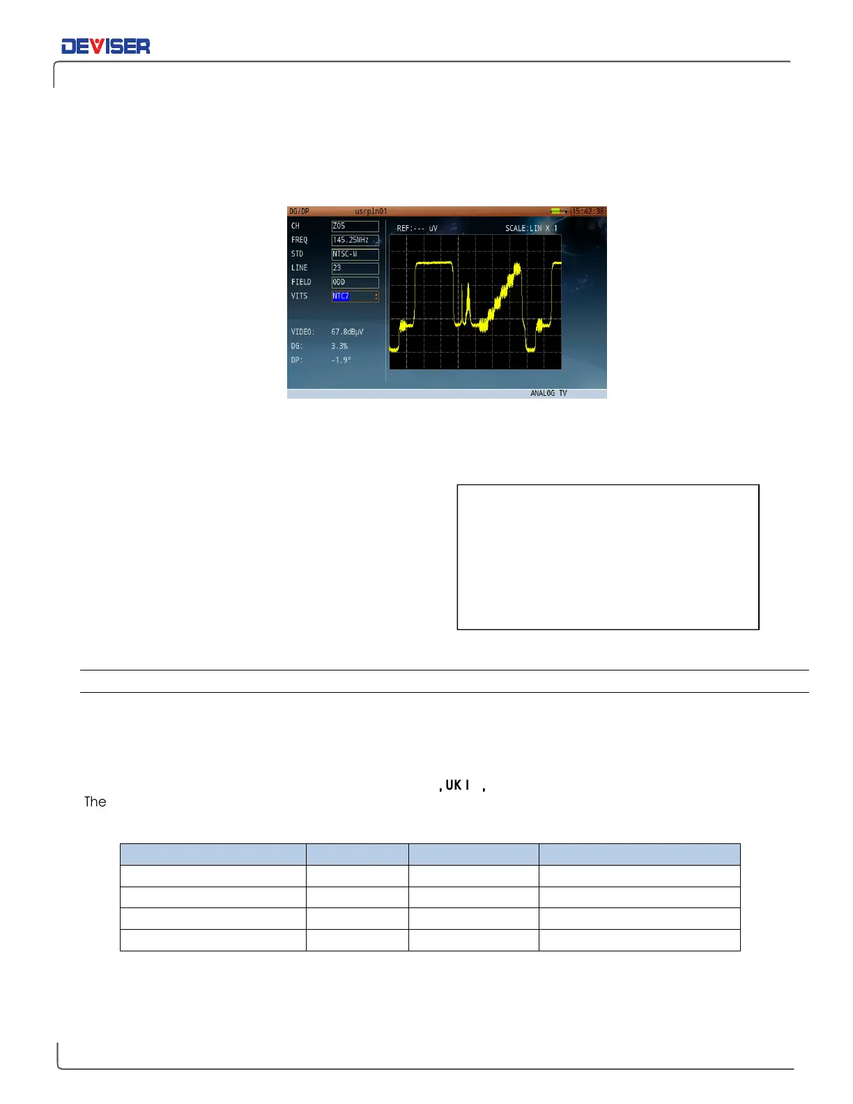
7-3 Differential Gain and Differential Phase
From the Channel Measurement application, press
DG/DP
to open the Differential Gain / Differential Phase
measurement menu.
Differential Gain and Differential Phase are defined as variations of the amplitude and phase of a Color
Sub-carrier superimposed on a luminance signal of varying IRE. Common practice is to use a luminance
variation in a stairstep (5 or 10 stairs), or a continuous ramp above the 0 IRE and reaching 90 IRE.
The measurement of Diff Gain & Phase is based on
variations of the demodulated color sub-carrier that is
the Color Vector. The amplitude and phase of the Color
Vector is measured at each step, and the peak-to-
peak variation is termed the Differential Gain & Phase.
Modern signal processing enables users to position the
sample locations on the test signal, while providing
measurement averaging and calculating the Peak-to-
peak variations & acceptance limits comparison.
7-3.1 Settings
The DG/DP function allows you to change the following settings. Possible values are listed when applicable.
VITS signal
:
Per frame 525 lines system, the VITS signal is:
FCC and NTC-7
Per frame 625 lines system, the VITS signal is:
CCIR330
,
,,
,
UK ITS
,
,,
,
GB19
The above VITS signals include the modulated staircase signal superimposed over the color subcarrier.
(Detailed VITS signal information is documented in Section 25-3 of this User Guide.)
Per frame 525 lines system: Field 1 (odd field), line 1-263; Field 2 (even field), line2-262
Per frame 625 lines system: Field 1 (odd field), line 1-313; Field 2 (even field), line2- 312
The IRE is a unit equal to 1/140 of the peak-
to-peak amplitude of the video signals –
typically 1 volt. The 0 IRE point is at blanking
level, with sync tip at -40 IRE and white
extending to +100 IRE. IRE stands for
Institute of Radio Engineers, the
organization that defined the unit.