Part II: Settings and Measurements
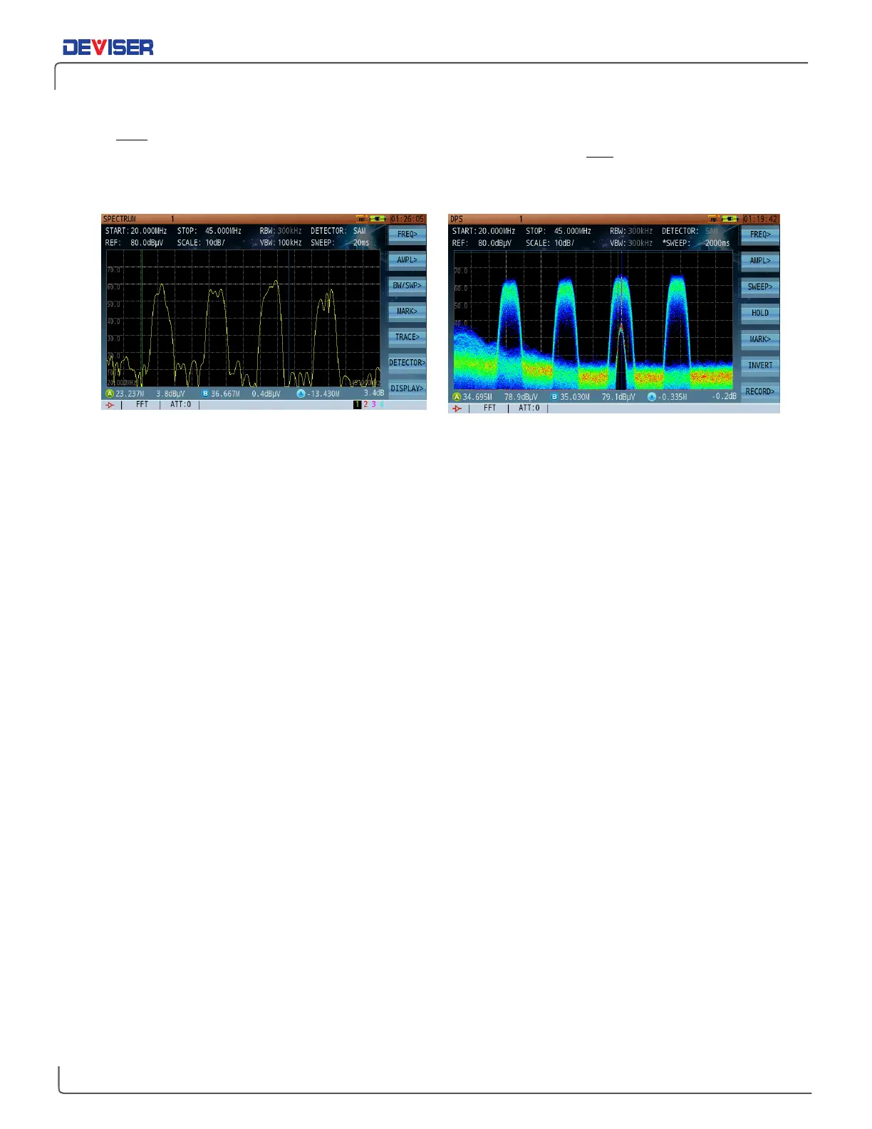
As shown below, when viewing a DOCSIS upstream channel in the normal spectrum analysis mode, you
can only
see the noise floor and the DOCSIS upstream signal transmission. Using the persistence mode, you
can easily and clearly identify both the DOCSIS upstream signal transmission and the underlying low level
interference signal normally covered by upstream signal and otherwise undistinguishable interference
signal. It is important to note that this method identifies the interference signal without service interruptions.
Low-Level Signals Covered by High-Level Signal Persistence Shows Ingress Signal Covered by DOCSIS Upstream Signal
11-3 Introduction to Persistence Application
In the Persistence mode, 4 markers are available: 2 vertical and 2 horizontal. When
MARK A
is highlighted,
vertical marker A is controlled with the rotary knob, and the horizontal marker with the arrow keys. In this
mode, because the measurement is made over a pre-selected period of time buffer, the amplitude range
of the same signal cannot be measured by a single vertical marker at any given frequency. Hence, the
need to use the horizontal marker to evaluate the level of the interference carrier.
It is recommended to use the vertical marker to best tune on the interferer frequency, and the horizontal
marker to measure the level of the interferer. Once the horizontal marker has been set to the peak level of
the interferer, press
To Ref
(F2) to set the horizontal marker as the reference level.
The persistence mode is fixed at sample detection by default. RBW and VBW are also fixed at 300 kHz each.
FFT sweep mode is also used by default and cannot be changed.
11-4 Persistence Recording
Persistence recording is related to several parameters. Possible values are listed where applicable.
Sweep Time: 100 ~ 5000ms.
Record Frames: 50 frames max.
Max Saved Files: 5 files.
The DS2831 offers two persistence recording methods: normal record and trigger record.