ENTRON Controls, LLC. • 700120S • Page 143
Before running production quantities of welded parts,
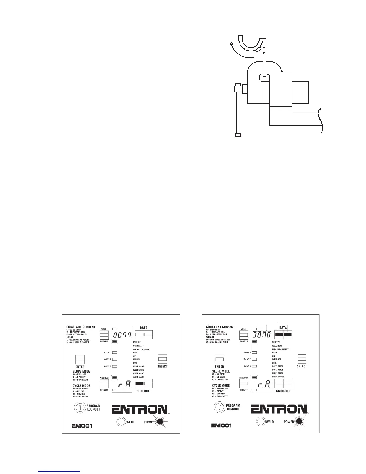
ENTRON recommends destructive testing of the welds.
Set the welding machine to RWMA recommended
standards. Weld the parts. Then clamp one end of the welded
part in a vise and PEEL the other side back against the
weld. Ideally, in low carbon steel, the weld will pull a hole
through one or the other parent materials.
To make the best possible weld for the material to
be welded, use:
1. The LOWEST transformer tap setting,
2. The HIGHEST PERCENT CURRENT setting, and
3. The SHORTEST WELD count setting.
B-2.0 CONSTANT CURRENT PROGRAMMING AND SETUP
(EN1001 only)
Put control in PROGRAM mode, as shown in Figure B-8. Find the EXTENDED FUNCTIONS
by pressing the SELECT push button until
EFEF
EFEF
EF appears in the DATA display. Use SCHEDULE
push buttons to scroll through the EXTENDED FUNCTIONS.
Based on Current Sensor and desired CONSTANT CURRENT mode, program
C.rC.r
C.rC.r
C.r
..
..
. and
rr
rr
r
.A..A.
.A..A.
.A. to
enable CONSTANT CURRENT. For
C.rC.r
C.rC.r
C.r
..
..
.=
3232
3232
32 or
3333
3333
33, only [kA] mode is possible, and
rr
rr
r
.A..A.
.A..A.
.A. must
be programmed according to desired RANGE (see Table 8-1). Programming [%] mode is shown
in Figure B-21, and programming RANGE of 30 kA for [kA] mode is shown in Figure B-22.
For programming four-digit data parameters, the two DATA push buttons are used as follows:
Press right DATA push button to increase by one, press and hold to increase by ten. Press left
DATA push button to increase by 100, and press and hold to increase by 1000.
After selecting and programming desired CONSTANT CURRENT mode, run setup if necessary.
Figure B-20. Destructive test
Figure B-21. Program RANGE for [%] mode
Figure B-22. Program RANGE for [kA] mode
APPENDIX B PROGRAMMING AND SETUP (cont.)

 Loading...
