EasyManuals Logo

Epson PowerLite 4100 User Manual

Epson PowerLite 4100
459 pages
To Next Page IconTo Next Page
To Previous Page IconTo Previous Page
Page #359 background imageLoading...
Page #359 background image
Operator's Guide B-13
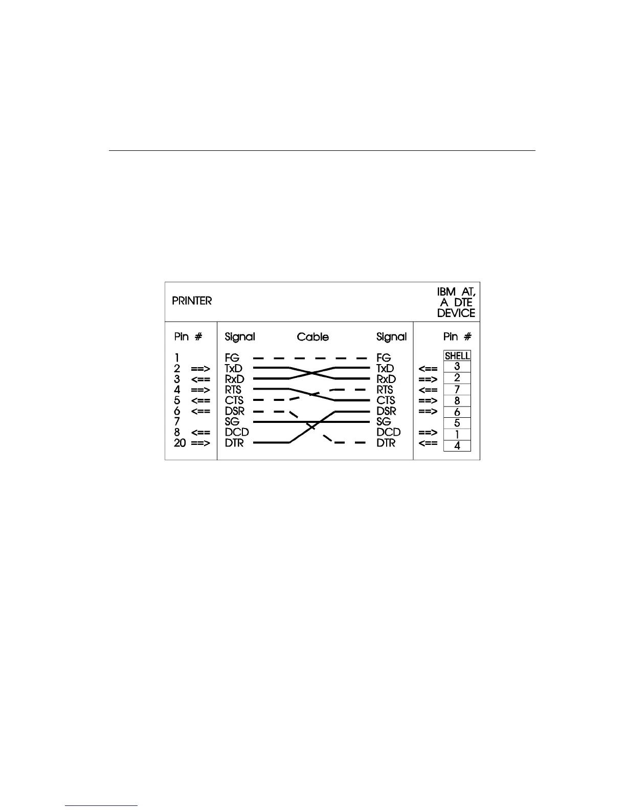
First, the Signal Ground on the printer is tied to the Signal Ground on the
IBM PC/AT; likewise, the Frame Grounds on the printer and IBM PC/AT
are tied together. Next, RxD on the printer (Pin 3) is tied to TxD (Pin 3) on
the IBM PC/AT; then TxD (Pin 2) on the printer is tied to RxD (Pin 2) on
the IBM PC/AT. Lastly, the control signals are connected: DTR (Pin 20)
on the printer to DSR (Pin 6) on the IBM PC/AT, and RTS (Pin 4) on the
printer to CTS (Pin 8) on the IBM PC/AT.
IBM PC/AT to Printer Wiring Diagram
AB0-AP

Table of Contents

Other manuals for Epson PowerLite 4100

Questions and Answers:

Question and Answer IconNeed help?

Do you have a question about the Epson PowerLite 4100 and is the answer not in the manual?

Epson PowerLite 4100 Specifications

General IconGeneral
BrandEpson
ModelPowerLite 4100
CategoryProjector
LanguageEnglish

Related product manuals