B-12 Appendix B—Serial Interface
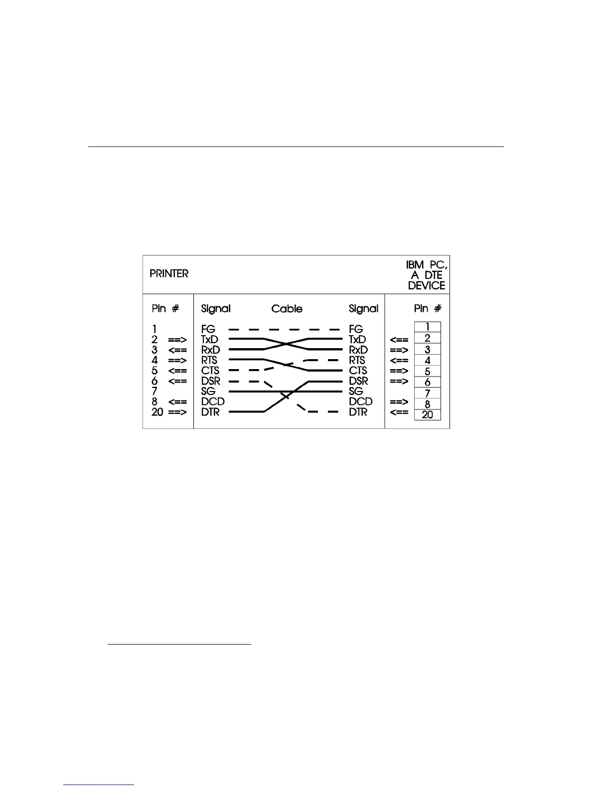
When the PC has data to send, it looks for a high voltage input on its Pin
5, CTS, before sending data. The printer actually holds the voltage
continuously high on its Pin 4, RTS, which is tied to the PC's Pin 5. Thus,
the PC automatically begins sending data on its Pin 2 and continue until
all data are sent or transmission is interrupted by a handshaking protocol.
IBM PC to Printer Wiring Diagram
AB0-AO
IBM PC/AT
*
TO PRINTER
The wiring diagram that follows shows how to connect an IBM PC/AT, a
DTE device, to the printer, also a DTE device. It differs from the IBM PC
example only in the pin numbers on the computer side. The IBM PC/AT
uses a male, 9-pin, D-type serial connector.
*
Also 386s, 486s, etc.