EPSON Stylus Pro 4400/4450/4800/4880/4880C Revision C
Operating Principles Printer Mechanism Components 122
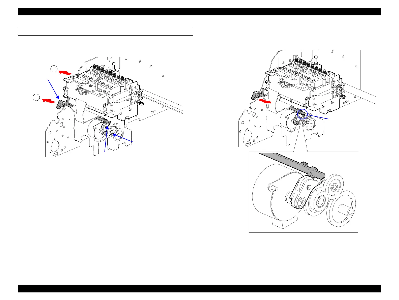
DRIVE TRANSMISSION TO PUMP UNIT
1. The DE Lock Lever is moved to the right end by moving the Carriage Unit
to the right end of the Carriage Shaft.
Figure 2-11. Switching Drive Transmission Path (1)
2. The ASF/Pump Motor rotates by the required step number in the clockwise
direction as seen from the Motor Pinion Gear side.
3. When the ASF/Pump Motor rotates in the clockwise direction, the
Planetary Lever inside the DE mechanism descends toward the
Combination Gear, 15.2, 25.6, and the Planetary Lever's Spur Gear, 15.2,
engages with the Combination Gear, 15.2, 25.6.
4. The DE Lock Lever fixes the Planetary Lever in place when the Carriage
Unit moves the required step number to the left from the Carriage Shaft
right end.
Figure 2-12. Switching Drive Transmission Path (2)
5. When the drive transmission path is switched by Step 1 through Step 4,
drive power of ASF/Pump Motor is transferred to the Pump Unit by the path
shown in Figure 2-8.
DE Lock Lever
1
2
Planetary Lever
Combination Gear, 15.2, 25.6
Fixing Location

 Loading...


