EPSON Stylus Pro 4400/4450/4800/4880/4880C Revision C
Disassembly & Assembly Disassembly Procedures 240
4.2.4.6 C593_SUB-D Board
1. Remove "Panel, Front/Panel Unit" (p219).
2. Disconnect all the connectors/harnesses on the "C593_SUB-D Board".
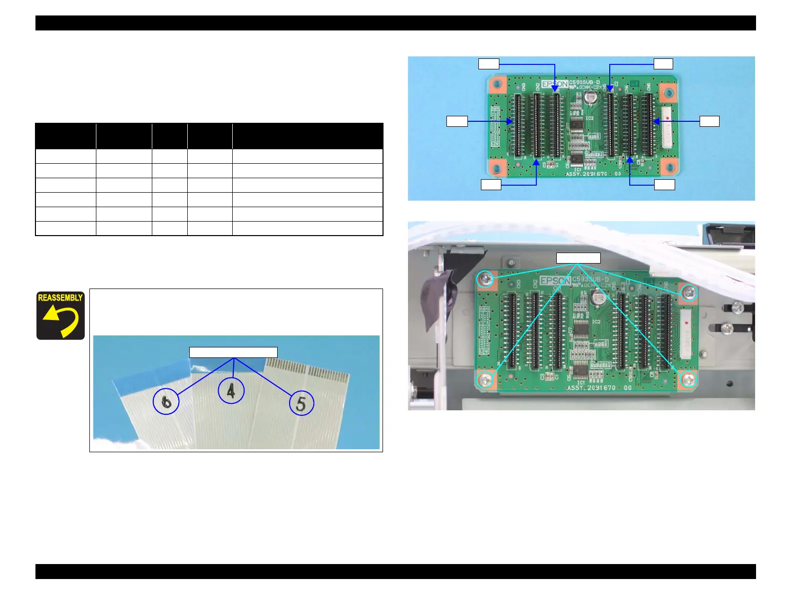
Note 1: Refer to Figure 4-47 for connector positions.The CN 45 is not used.
2: When connecting harnesses to the C593_SUB-D Board, connect them in the
order shown in Table 4-9.
3. Remove the four screws securing "C593_SUB-D Board" and remove
"C593_SUB-D Board".
C.B.P. 3x6: 4 pcs.
Figure 4-49. C593_SUB-D Board Connector Positions
Figure 4-50. C593_SUB-D Board Removal
Table 4-9. Connectors/Harnesses Connected to C593_SUB-D Board
Connection
Order
Connector
No.
Color/
Mark
Number
of Pins
Connection Socket
1 CN1 - 31 C593 MAIN Board (CN7)
2 CN2 - 31 C593 MAIN Board (CN8)
3 CN3 - 30 C593 MAIN Board (CN9)
4 CN4 - 30 C593 SUB Board (CN1)
5 CN5 - 31 Print Head Board (CN1)
6 CN6 - 31 Print Head Board (CN2)
Each "Harness, Head, Intermit" and "Harness, Head" is
marked with its connector No. Refer to Table 4-9 and
connect the harnesses properly.
Connector Numbers
CN3
CN1
CN6
CN4
CN5
CN2
C.B.S. 3x6

 Loading...


