EPSON Stylus Pro 4400/4450/4800/4880/4880C Revision C
Disassembly & Assembly Disassembly Procedures 288
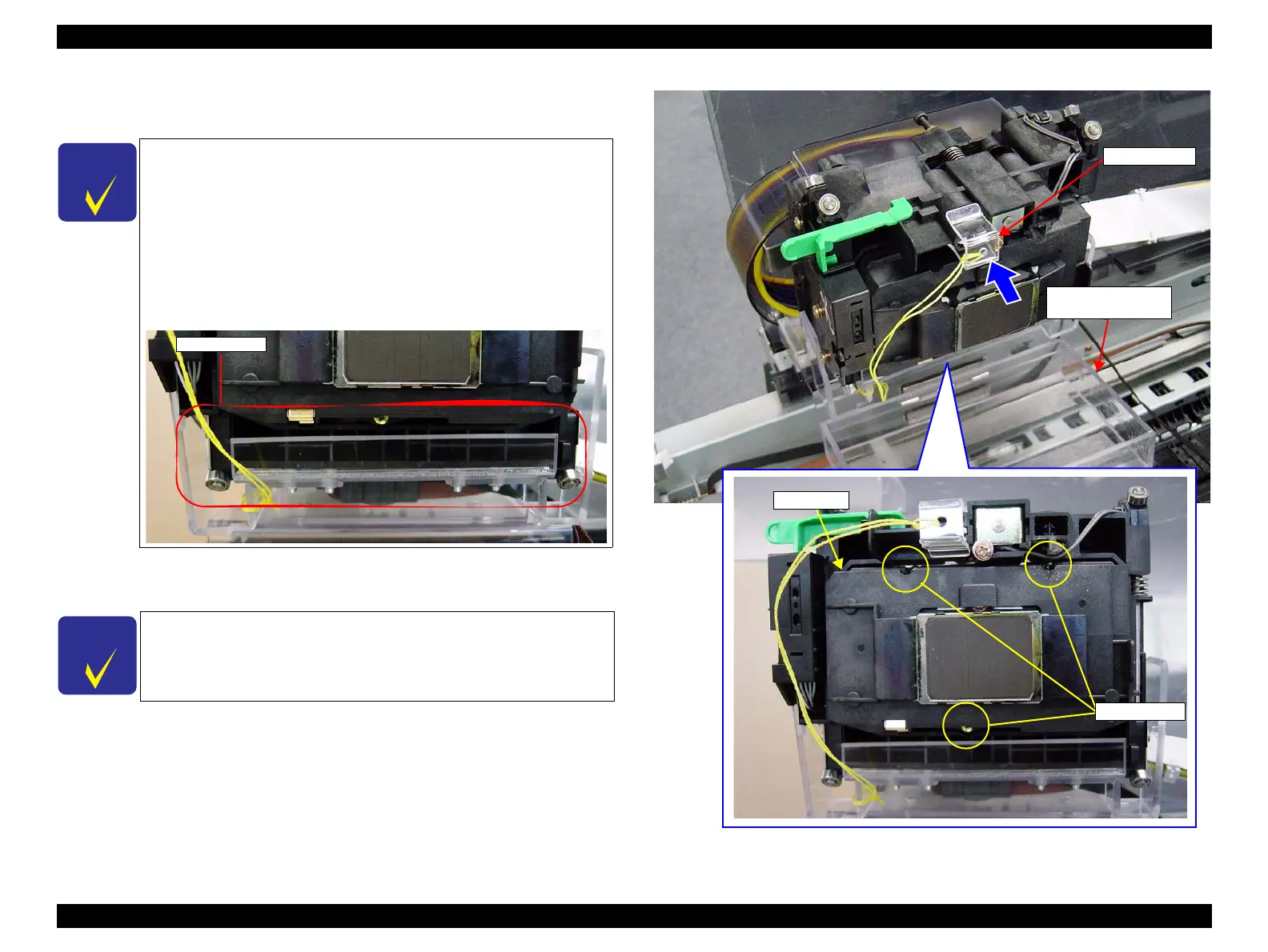
8. Set the "Carriage Unit" on the "HEAD EXCHANGE SUPPORT TOOL".
(Refer to Figure 4-110.)
9. Attach the "CUTTER CAP" to the cutter section of the "Carriage Unit".
(Refer to Figure 4-110.)
10. Remove the three screws that secure the "Carriage, C" from the bottom of
the "Carriage Unit".(Refer to Figure 4-110.)
C.C.P. 2.6 x 8: 3 pcs.
Figure 4-110. Carriage Unit Setting / Screws Securing Carriage, C
C H E C K
P O I N T
When setting the "Carriage Unit" on the "HEAD
EXCHANGE SUPPORT TOOL", take care not to bend the
"Tube, Supply, Ink". If it get bend, replace with a new
one.
Make sure the "Carriage Unit" is installed to the "HEAD
EXCHANGE SUPPORT TOOL" securely.
Make sure that the "Carriage Unit" is completely set into
the position with its bottom is parallel to the tool as seen
from the side of the "Carriage Unit".
C H E C K
P O I N T
The "CUTTER CAP", which covers the cutter blade projecting
upward from the bottom of the Carriage, prevents injury
during the work.
Check Point
CUTTER CAP
C.P.P. 2.6x8
Carriage, C
HEAD EXCHANGE
SUPPORT TOOL

 Loading...


