EPSON Stylus Pro 4400/4450/4800/4880/4880C Revision C
Operating Principles Outline of Control Circuit Board 152
2.3 Outline of Control Circuit Board
This section describes the operation of BOARD ASSY., MAIN, which controls
and drives the Printer Mechanism of Stylus Pro 4400/4450/4800/4880/4880C.
C593 MAIN Board: Stylus Pro 4400/4800
CA00 MAIN Board: Stylus Pro 4450/4880/4880C
NOTE: For circuit board details, refer to "Chapter 7: Appendix (p.457)
at the end of this volume.
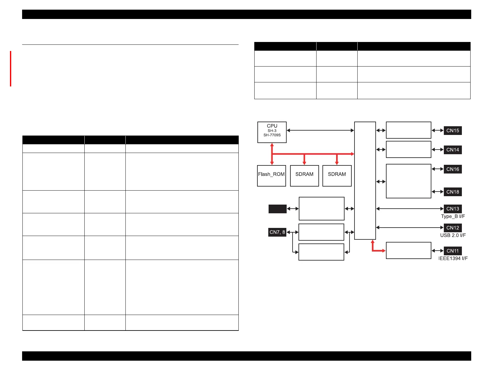
Explanation of major elements
Figure 2-62. C593 MAIN Board – Circuit Block Diagram
Table 2-14. Major Elements
Model No. Location Function
SDRAM IC2/23 System memory 64MB (256Mbit x 2)
Flash ROM IC12 Flash Memory 2MB (1Mbit x 16bit)
• For storage of control program
(firmware)
• Saving of various setting parameters
and control information
SH-3
SH-7709S
IC15 32bit RISC-CPU
• Operational frequency: Internal 96MHz
External 48MHz
E09A54RA IC17/18 Custom ASIC
• Head drive voltage waveform generation
control
RTC9824SA IC16 Real-Time Clock
• Sets year/month/day by F/W
• MAIN PCB reset signal formation
E05C25BB IC19 Custom ASIC
1. Print data processing
• Rasterizer
• Head drive control
2. Mechanism control
(motors and solenoids)
3. Sensor control
TSB43AA82A IC4 ASIC
• IEEE1394-I/F control
A3958SLBTR-T IC5 CR Motor driver
• PWM current control method
A3958SLBTR IC6 PF Motor driver
• PWM current control method
AA6628SEDTR-T IC7 • ASF/Pump Motor driver
• PG/PO Motor driver
Table 2-14. Major Elements
Model No. Location Function
PF motor driver
ASF/pump motor
PG/PO motor
driver
Real-Time Clock
Custom ASIC
ASIC
Custom ASIC
CR motor
PF motor
ASF/pump
motor
PG/PO moto
Custom
ASIC
Head FFC
Lithium battery
BAT1
RTC9824SA
(IC16)
E05C25BB
(IC19)
A3958SLBTR-T
(IC5)
A3958SLBTR
(IC6)
A6628SEDTR-T
(IC7)
TSB43AA82A
(IC4)
(IC12)
(IC15)
(IC2) (IC23)
E09A54RA
(IC17)
E09A54RA
(IC18)
CR motor driver

 Loading...


