EPSON Stylus Pro 4400/4450/4800/4880/4880C Revision C
Disassembly & Assembly Disassembly Procedures 303
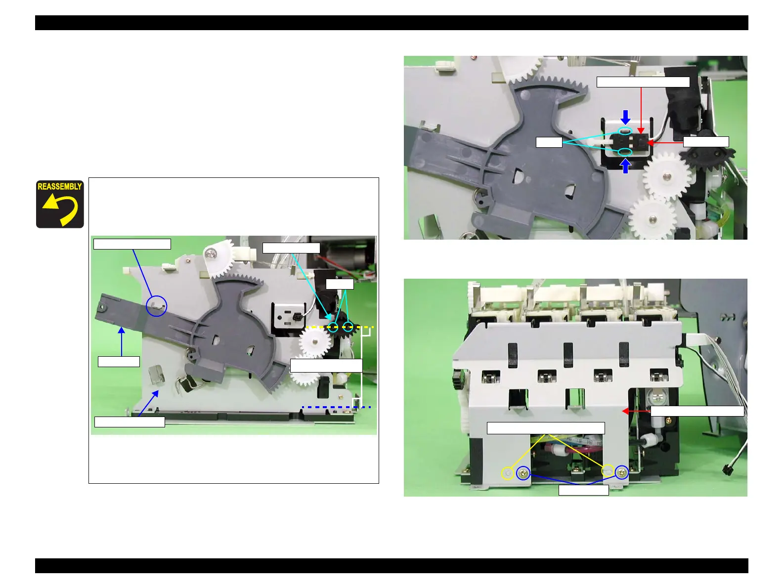
17. Pick up and release the two tabs securing the "I/H Lever Sensor (Left)" and
remove the "I/H Lever Sensor (Left)". (Refer to Figure 4-133.)
18. Disconnect connector from "I/H Lever Sensor (Left)"
(Refer to Figure 4-133.)
19. Remove the two screws securing "Cover, Holder, IC, Left" and remove
"Cover, Holder, IC, Left".
(Refer to Figure 4-134.)
C.B.S. 3x6: 2pcs.
Figure 4-133. I/H Lever Sensor (Left) Removal
Figure 4-134. Cover, Holder, IC, Left Removal
When the "Ink Lever" is installed against the angle set
location as shown in the illustration, confirm that the two
holes of "Fan Gear, 34" form a line parallel to the bottom
of "Frame, Holder, IC".
Align the two dowels on holder side with the two
positioning holes on the "Cover, Holder, IC".
(Refer to Figure 4-134.)
Ink Lever
Angle Set Location
Holes
Parallel Alignment
Frame, Holder, IC
Fan Gear, 34
I/H Lever Sensor (Left)
Tabs
Connector
Dowels and Positioning Holes
C.B.S. 3x6
Cover, Holder, IC, Left

 Loading...


