EPSON Stylus Pro 4400/4450/4800/4880/4880C Revision C
Disassembly & Assembly Disassembly Procedures 320
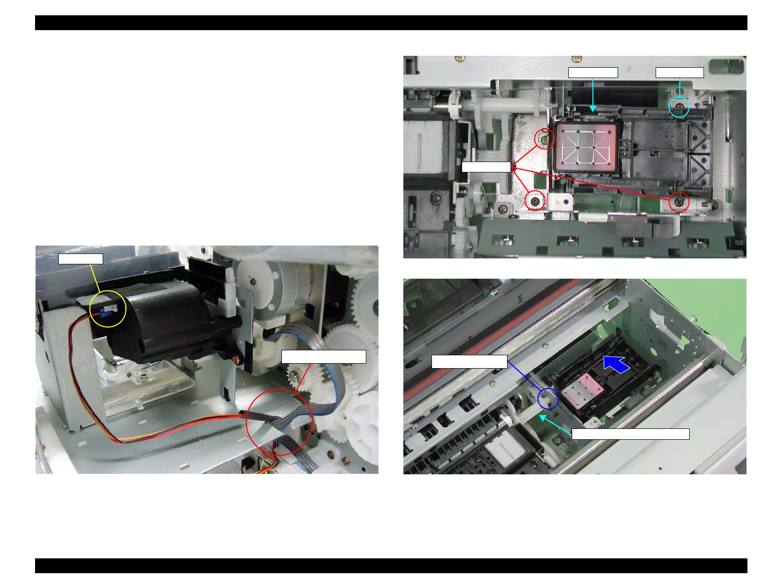
10. Disconnect the connector from the "Pump Phase Sensor" from behind the
printer. (Refer to Figure 4-159.)
11. Free all the harnesses from the U-shaped notch of the "Frame, Base, Side,
Right". (Refer to Figure 4-159.)
12. Remove the four screws securing the "Pump Unit". (Refer to Figure 4-160.)
C.B.S. 3x6: 3 pcs.
C.B.S. 3x8: 1 pc.
13. Shift the "Pump Unit" to the right side and disconnect the linkage with
"Combination Gear, 13.6, 28.8". (Refer to Figure 4-161.)
14. Remove "Pump Unit" toward rear. (Refer to Figure 4-161.)
Figure 4-159. Disconnecting the Pump Phase Sensor Connector
Figure 4-160. Screws Securing Pump Unit
Figure 4-161. Pump Unit Removal
Connector
Releasing Harnesses
Pump Unit C.B.S. 3x8
C.B.S. 3x6
Linkage Location
Combination Gear, 13.6, 28.8

 Loading...


