EPSON Stylus Pro 4400/4450/4800/4880/4880C Revision C
Disassembly & Assembly Disassembly Procedures 238
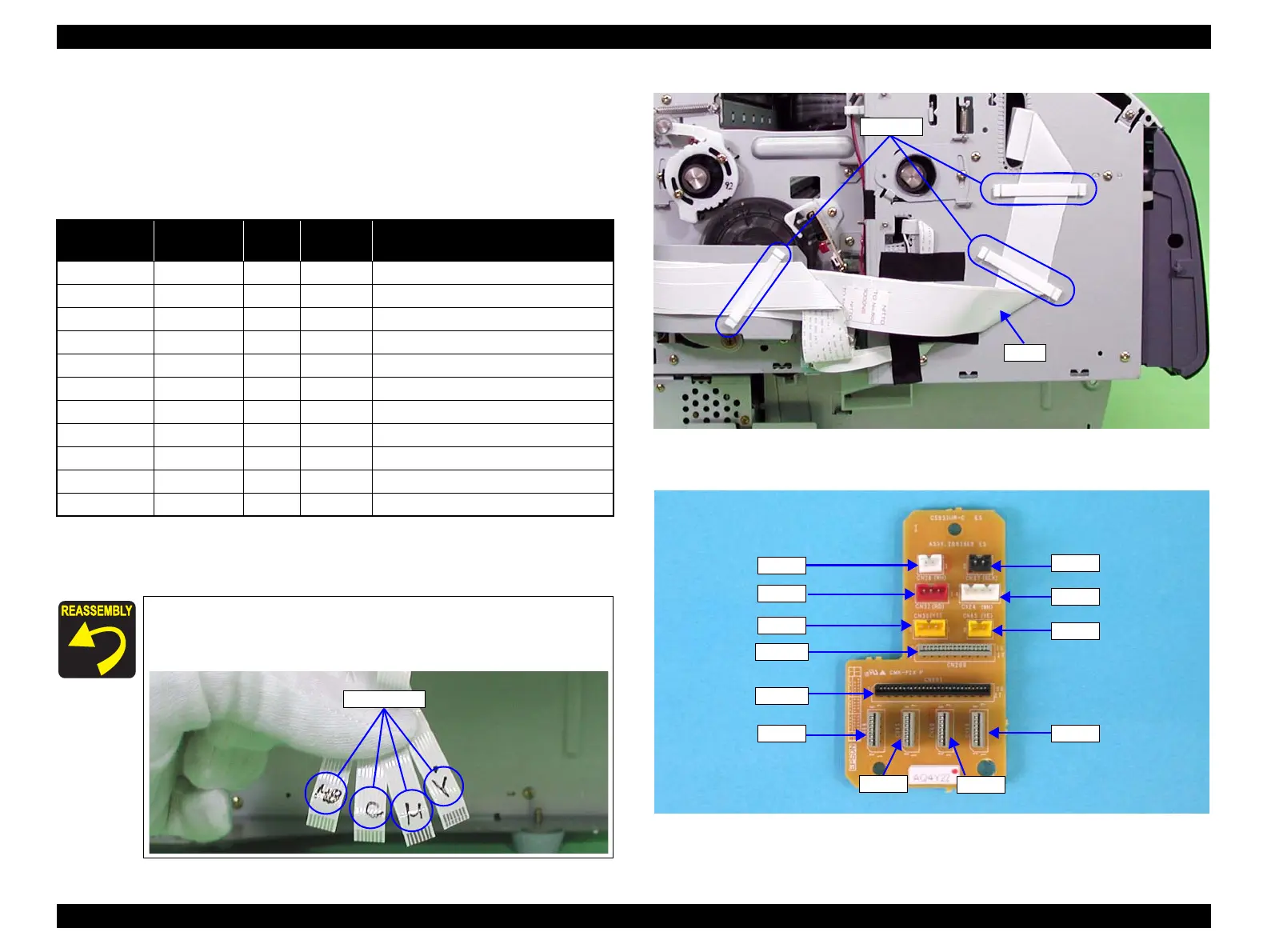
4.2.4.5 C593_SUB-C Board
1. Remove "Cover, Side, Left" (p216).
2. Release the FFC from the three clamps.
3. Disconnect all connectors/harnesses on the "C593_SUB-C Board".
Note 1: Refer to Figure 4-47 for connector positions.The CN 45 is not used.
2: When connecting harnesses to the C593_SUB-C Board, connect them in the
order shown in Table 4-8.
Figure 4-46. Releasing FFC
Figure 4-47. C593_SUB-C Board Connector Locations
Table 4-8. Connectors/Harnesses Connected to C593_SUB-C Board
Connection
Order
Connector
No.
Color/
Mark
Number
of Pins
Connection Socket
1 CN38 MB 7 CSIC_L1 Board (Matte Black)
2 CN40 C 7 CSIC_L2 Board (Cyan)
3 CN41 M 7 CSIC_L3 Board (Magenta)
4 CN44 Y 7 CSIC_L4 Board (Yellow)
5 CN201 - 28 C593 MAIN Board (CN53)
6 CN200 - 15 C593 MAIN Board (CN52)
7 CN24 White 4 PF Linear Encoder Sensor
8 CN37 Black 2 I/H Lever Sensor (Left)
9 CN30 Yellow 3 ASF Phase Sensor
10 CN28 White 2 Paper Eject Phase Sensor
11 CN32 Red 3 PG Phase Sensor
Each "Harness, CSIC" (CN38, CN40, CN41, CN44) is marked
with its corresponding ink name. Refer to Table 4-8 and
connect the harnesses properly.
Ink Names
Clamps
FFC
CN45
CN24
CN37
CN28
CN200
CN201
CN30
CN44
CN41
CN40
CN38
CN32

 Loading...


