7700 Multiframe Manual
7725DSK-LG / 7725DSK-LG-HD HD/SD Logo Inserter & Media Keyer
Page 2-4 Revision 1.4 INSTALLATION
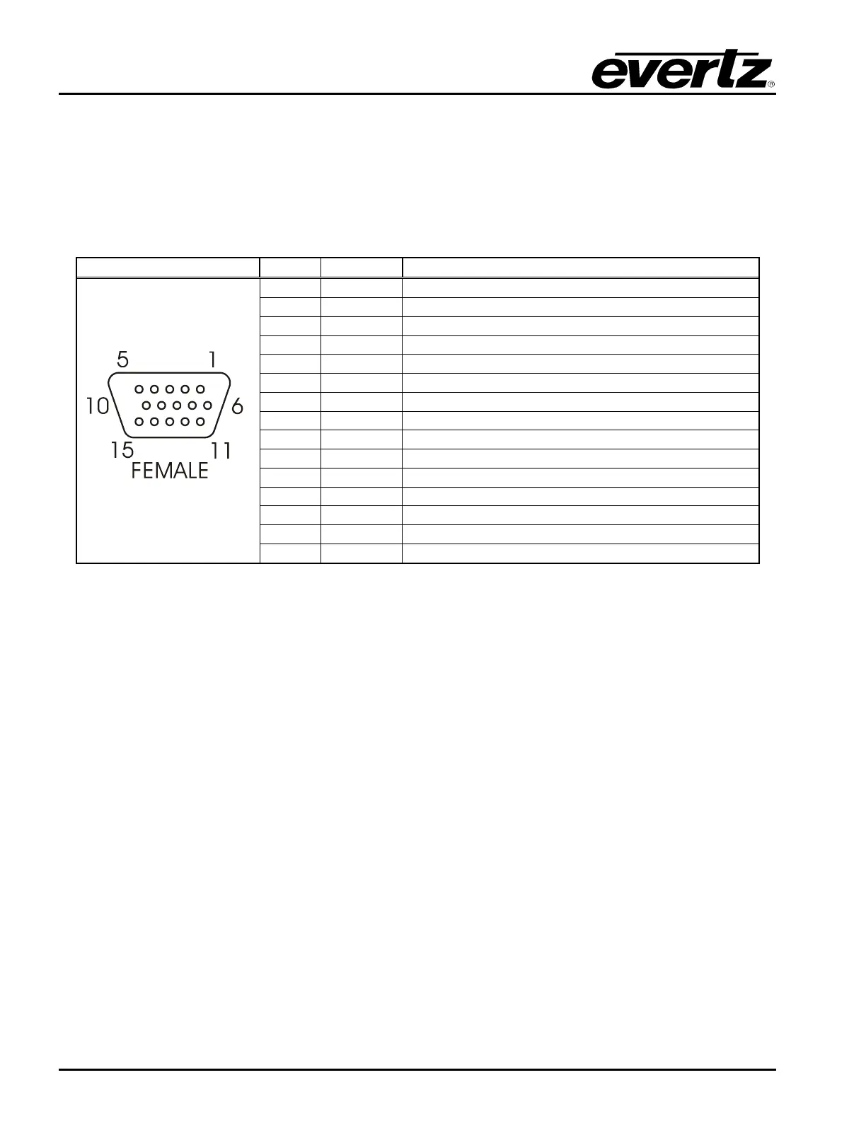
2.1.4. GPI/O Connections
GPI/O: This 15 pin female high density ‘D’ connector (AUX I/O) contains several general-purpose
control inputs and outputs. The inputs are used to connect manual or automatic triggers for
the display or insertion of media. The outputs provide feedback on internal unit status of the
downstream keyer. See section 2.8 for information on connecting the general-purpose
inputs and outputs. For information on configuring the GPI and GPO functions, see section
3.8 for VLPRO Configuration and sections 4.11.1 and 4.11.2 for RCP Configuration.
Pin # Name Description
1
GND Chassis ground
2
GPOUT1 General purpose output B
3
GPOUT0 General purpose output A
4
GPOUT2 General purpose output C
5
GPIN2 General Purpose Input C
6
GPOUT3 General Purpose Output D
7
GPIN5 General Purpose Input F
8
GPIN0 General Purpose Input A
9
GPIN3 General Purpose Input D
10
+3.3V Power
11
GPIN7 General Purpose Input H
12
GPIN4 General Purpose Input E
13
GPIN6 General Purpose Input G
14
GPIN1 General Purpose Input B
15
VEXT External Power Supply for the Inputs2
Table 2-4: GPI/O Connector Pin Definitions
2.1.5. Ethernet Network Connections
ETHERNET: This RJ-45 connector is an Ethernet port used for high-speed firmware upgrades and
FTP logo transfers. This Ethernet port also facilitates control via VistaLINK
®
PRO or
Overture software (refer to section 3). See section 2.7 for information on connecting to an
Ethernet network. See section 4.6.5 in the General menu descriptions for information on
configuring the network addresses for the downstream keyer.
2.2. MOUNTING
The rack mount Remote Control Panel (RCP) is equipped with rack mounting angles and fits into a
standard 19 inches by 1.75 inches by 3.75 inches (483 mm x 45 mm x 150mm) rack space. The
optional Desktop Remote Control Panel (DCP) is designed to be mounted on a control panel desk and
is fitted with rubber feet to keep it from sliding on the desktop.