7700 Multiframe Manual
7725DSK-LG / 7725DSK-LG-HD HD/SD Logo Inserter & Media Keyer
INSTALLATION Revision 1.4 Page 2-7
2.6. CONNECTING THE LINEAR TIME CODE
The 7725DSK-LG has a linear time code (LTC) input used to provide time information for the analog or
digital clock logos. Connect the LTC output from your house master time code source to the LTC IN
XLR connector. When using an unbalanced input to the reader, the signal should be applied to pin 3 of
the reader input connector. Normally, the unused input (pin 2) should be connected to ground (pin 1).
2.7. CONNECTING TO AN ETHERNET NETWORK
The 7725DSK-LG is designed to be used with either 10Base-T (10 Mbps) or 100Base-TX (100 Mbps)
also known as Fast Ethernet, twisted pair Ethernet cabling systems. When connecting for 10Base-T
systems, category 3, 4, or 5 UTP cable as well as EIA/TIA – 568 100Ω STP cable may be used. When
connecting for 100Base-TX systems, category 5 UTP cable is required. The cable must be “straight
through” with a RJ-45 connector at each end. Create a network connection by plugging one end of the
cable into the RJ-45 receptacle of the 7725DSK-LG and the other end into a port of the supporting
network device.
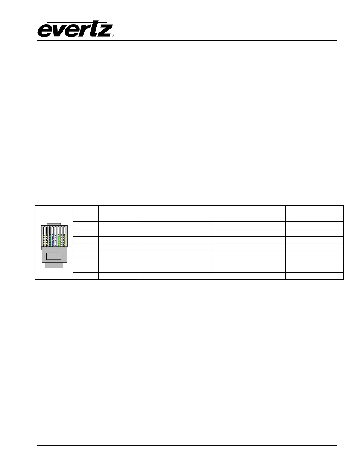
The straight-through RJ-45 cable can be purchased or can be constructed using the pinout information
in Table 2-7. A colour code wiring table is provided in Table 2-7 for the current RJ 45 standards
(AT&T 258A or EIA/TIA 258B colour coding shown). Also refer to the notes following the table for
additional wiring guide information.
Pin # Signal EIA/TIA 568A
AT&T 258A or
EIA/TIA 568B
10BaseT
or 100BaseT
1
Transmit + White/Green White/Orange X
2
Transmit – Green/White or White Orange/White or Orange X
3
Receive + White/Orange White/Green X
4
N/A Blue/White or Blue Blue/White or Blue Not used (required)
5
N/A White/Blue White/Blue Not used (required)
6
Receive – Orange/White or Orange Green/White or Green X
7
N/A White/Brown White/Brown Not used (required)
Pin 1
8
N/A Brown/White or Brown Brown/White or Brown Not used (required)
Table 2-7: Standard RJ45 Wiring Colour Codes
Note the following cabling information for this wiring guide:
• Only two pairs of wires are used in the 8-pin RJ 45 connector to carry Ethernet signals.
• Even though pins 4, 5, 7 and 8 are not used, it is mandatory that they be present in the cable.
• 10BaseT and 100BaseT use the same pins; a crossover cable made for one will also work with the
other.
• Pairs may be solid colours and not have a stripe.
• Category 5 cable must use Category 5 rated connectors.
The maximum cable run between the downstream keyer and the supporting hub is 300 ft (90 m). The
maximum combined cable run between any two end points (i.e. downstream keyer and PC/laptop via
network hub) is 675 feet (205 m).
Devices on the Ethernet network continually monitor the receive data path for activity as a means of
checking that the link is working correctly. When the network is idle, the devices also send a link test
signal to one another to verify link integrity. The downstream keyer rear panel is fitted with two LEDs to
monitor the Ethernet connection.