7700 Multiframe Manual
7725DSK-LG / 7725DSK-LG-HD HD/SD Logo Inserter & Media Keyer
INSTALLATION Revision 1.4 Page 2-5
2.3. POWER REQUIREMENTS
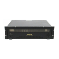
The standard 7725DSK-LG is a 2 slot card contained within the 7700FR. The 7700FR-C frame comes
standard with one auto-ranging power supply that automatically senses the input voltage over the
range of 100 to 240 VAC. An additional power supply (7700PS) can be ordered to provide fully
redundant powering of the frame. When only one power supply is fitted, the frame will be fitted with a
7700PS-FM fan module to ensure the thermal integrity of the frame cooling. Power should be applied
by connecting a 3-wire grounding type power supply cord to the power entry module on the rear panel
of each power supply. The power cord should be minimum 18 AWG wire size; type SVT marked VW-1,
maximum 2.5m in length.
The power entry modules contain a standard IEC power inlet connector, two 5 x 20 mm fuse holders
and an EMI line filter.
CAUTION – TO REDUCE THE RISK OF ELECTRICAL SHOCK, GROUNDING
OF THE GROUND PIN OF THE MAINS PLUG MUST BE MAINTAINED.
2.4. CONNECTING THE REMOTE CONTROL PANEL
The 7725DSK-LG is available with a rack mountable or desktop remote control panel. The remote
control panel is connected to the SERIAL CONTROL connector on the Keyer units using COM B of the
breakout cable (Evertz Part # WP-SERIAL-COM-1-0), provided. For longer distances, simply make
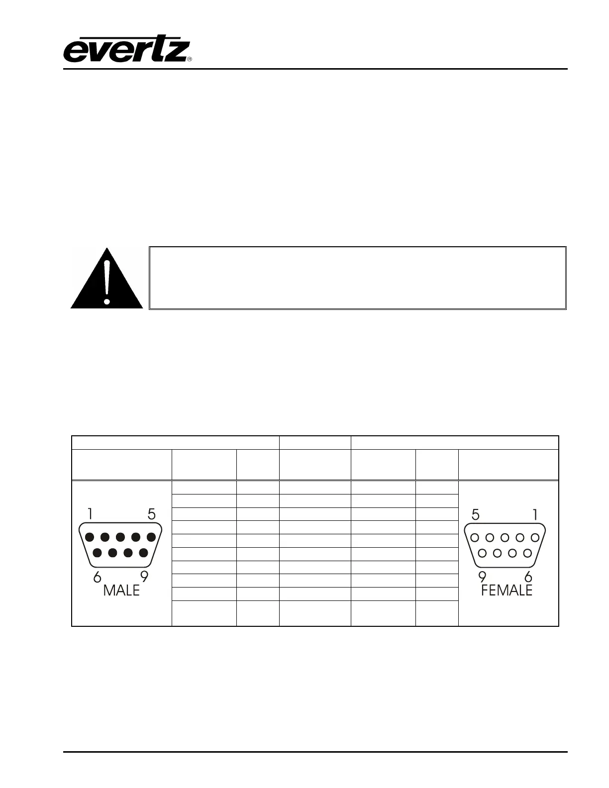
your own cable of the required length according to the diagram in Table 2-5. Communications to the
remote panel is through a standard straight-through RS-422 connection, enabling the panel to be
located up to 1000 feet from the main electronics unit.
7725DSK-LG End Remote Panel End
9 pin D
Male
Pin
Belden
9729
9 pin D
Female
Pin
1
1
Tx-
2
-------1a------ Rx-
2
Rx+
3
-------2b------ Tx+
3
Rx Gnd
4
---drain 2---- Rx Gnd
4
5
Tx Gnd
6
---drain 1---- Tx Gnd
6
Tx+
7
-------1b----- Rx+
7
Rx-
8
-------2a------ Tx-
8
9
9
Frame
Gnd
Shield
---drain 1----
Frame
Gnd
Shield
Table 2-5: Remote Control Panel Extender Cable