990DSL
Users Guide
2-2
The CopperPro Loop Tester: at a Glance
This section acquaints you with the physical layout of the CopperPro.
Front Panel
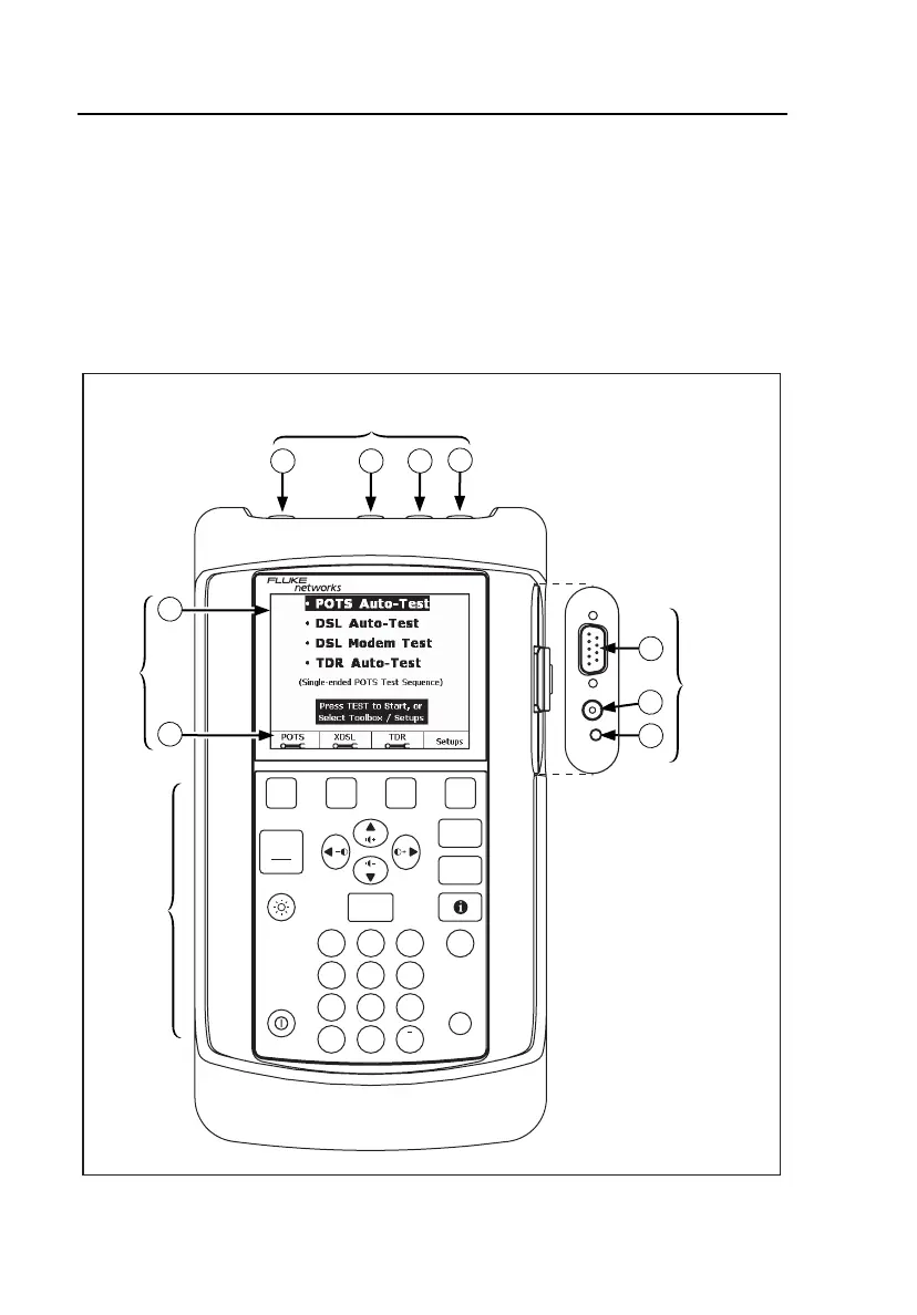
Figure 2-1 identifies the elements on the tester’s front, top, and side panels.
Following the figure are descriptions of the numbered items in the illustration.
C
OPPER
P
RO
S
ERIES
II990DSL
BROADBAND LOOP TESTER
USER OPTIONS
PRINT SCREEN
HOME
ENTER
.
ABC DEF
GHI JKL
MNO
PQRS
TUV
SPACE
WXYZ
1
4
56
78
0
9
2
3
#
*
START
STOP
TEST
SAVED
RESULTS
BACK
1
2
3 4
DIAL
es T to St r
or Select T olbox / Setups
•
1
1
1
2
3
2 3
4
2
LCD
Keypad
Side
connector
panel
Top connector panel
(test lead jacks)
elf02f.eps
Figure 2-1. Top, Front, and Side Panels