990DSL
Users Guide
4-22
Resistance Fault Location (RFL) Test
The RFL test provides a highly accurate method of locating resistance faults
(shorts, grounds, or crosses), including those that are too large for the TDR
test to locate. It does this by using cable gauge and temperature values in a
“nulling bridge” process. In this process, half of a resistance bridge is formed
within the tester, and the faulted pair (strapped at the far end, as prompted)
forms the other half of the bridge. The internal bridge ratio is then changed
until it precisely mirrors the ratio of the faulted leg to the good leg, and is then
used to calculate resistance values to the fault and strap.
Setting Up an RFL Test
To set up an RFL test, select the test on the POTS Toolbox and press
D(
Setups). Refer to Table 4-5 for RFL test setup parameters.
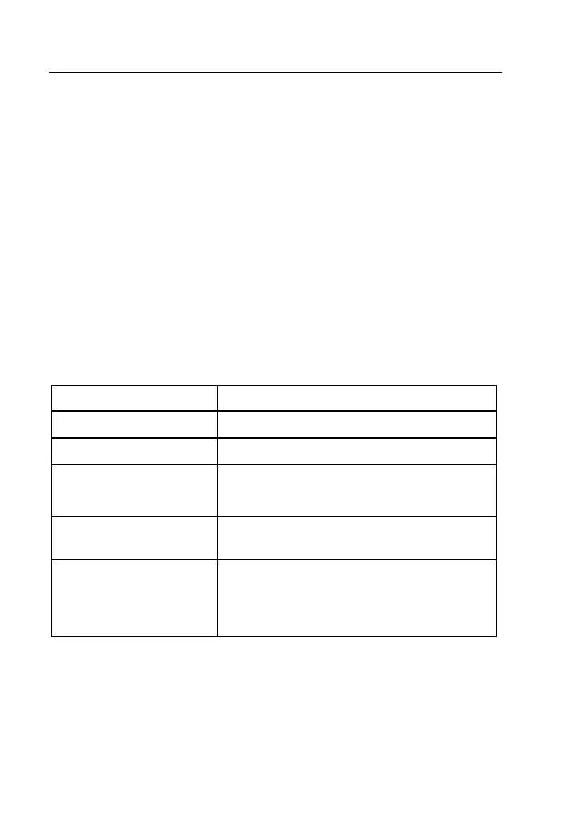
Table 4-5. RFL Test Setup Parameters
Parameter Settings (default in bold)
Cable Gauge 19, 22, 24, 26, or 28 AWG
Cable Temperature 68° F (Range = –99 to 199)
Measurement Mode Normal or High AC Rejection
(See POTS Auto-Test Setups for details)
RFL Fault Pass
Threshold
30 M e (Range = 1 Me to 30 M e)
Multiple Gauge Entry
Limits
Section Length (Range = 0 to 9999 ft.)
Gauge / mm (Same as Cable Gauge)
Load (Y or N)