990DSL
Users Guide
4-12
Shorts & Grounds Test
The Shorts & Grounds test provides a “snapshot” measurement of the
resistances between each leg (TR, TG, and RG) of a pair.
Setting Up a Shorts & Grounds Test
To set up a Shorts & Grounds test, select the test on the POTS Toolbox and
press D(
Setups). Refer to Table 4-3 for test setup parameters.
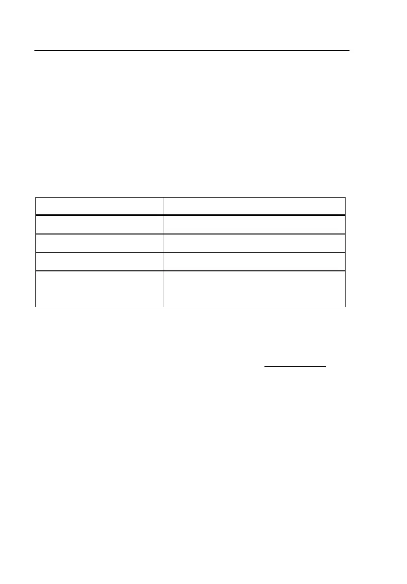
Table 4-3. Shorts & Grounds Test Setup Parameters
Parameter Settings (default in bold)
Resist. Fault Pass Threshold ≥150 Ke (Range = 2 to 9999)
Cable Gauge 19, 22, 24, 26, or 28 AWG
Cable Temperature 68° F (Range = –99 to 199)
Measurement Mode Normal or High AC Rejection
(See POTS Auto-Test Setups for details)
Shorts & Grounds Test Results
To run a Shorts & Grounds test, select it on the POTS Toolbox and press K.
In Figure 4-6, the Shorts & Grounds test detected a short (
Tip-Ring Short) on
the pair, due to a fault resistance reading (
500 Ω) that is outside the acceptable
limits (as defined in the setup for the test). This reading is shown in flashing,
reverse video format.