24 MDS Orbit MCR/ECR Technical Manual MDS 05-6632A01, Rev. F
NOTE The unit is designed for use in negative ground DC power systems only. Only use the power
supply provided by the manufacturer for the product or a certified LPS power supply rated for
nominal power 11-55 VDC, 4.5 A maximum must be used. Otherwise, safety of the product
may be impaired. In case of doubt, please consult the local authorized suppliers.
Input voltage to the unit must be well filtered and within the nominal range of 11-55 VDC . The
maximum rated power consumption of the device is 15 watts, but actual power may be much less,
depending on configuration. The power supply must be capable of supplying the expected maximum
power for the installation. For expected power requirements in common configurations, see “Technical
Specifications” on Page 383.
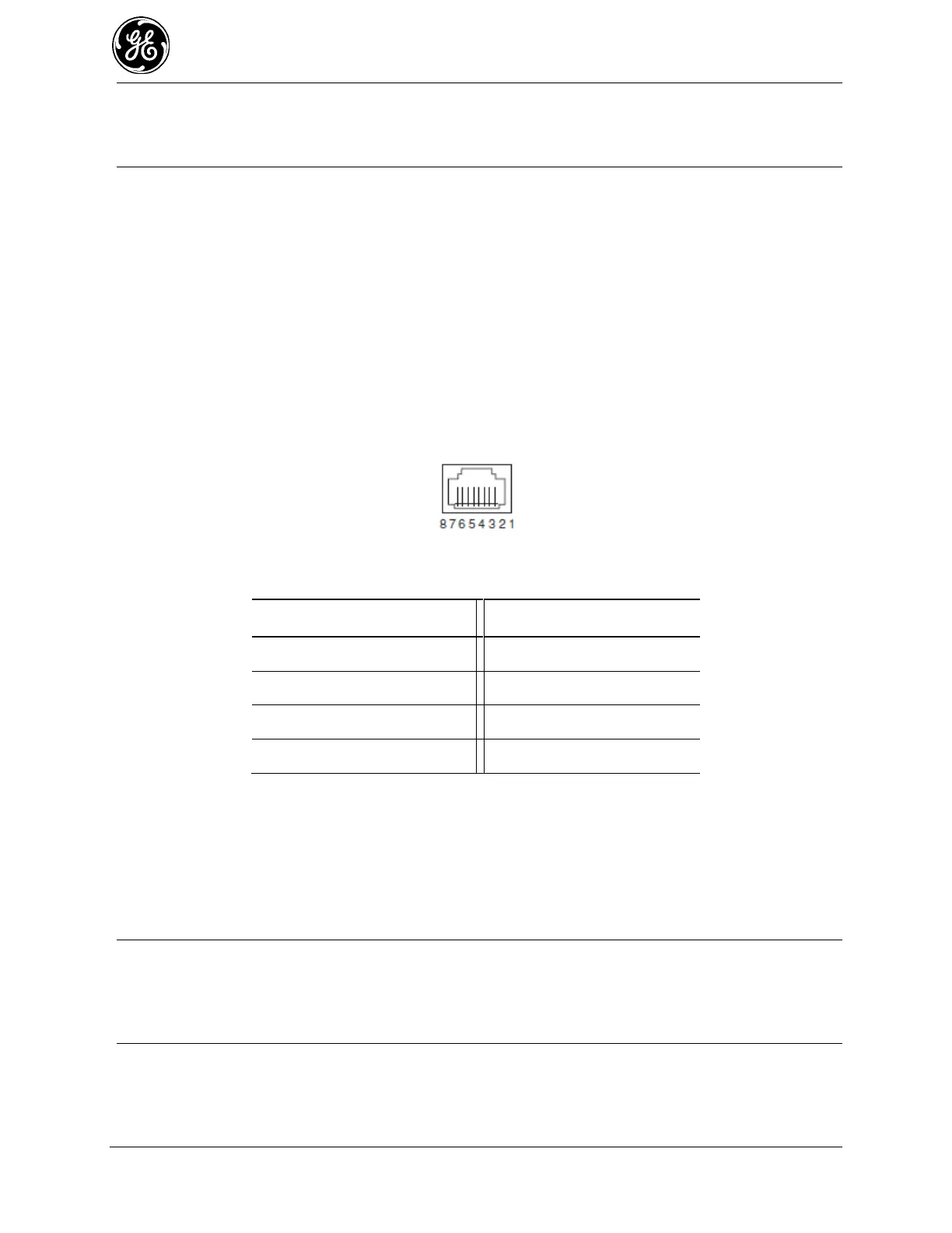
ETH1 / ETH2— Ethernet connection port. These ports support both device management and payload
data transport. Depending on ordered options, the unit may have one or two Ethernet ports. This is a
standard RJ-45 jack and features MDIX auto-sensing capability, allowing straight-through or crossover
cables to be used.
Connecting to the unit via SSH supports device management and provides the same user interface
available using the unit’s COM1 serial port. Various options are available for passing Ethernet data,
allowing system administrators to optimize the configuration for maximum efficiency, based on the
system’s operating characteristics.
(As viewed from the outside the unit)
Table 2-1. ETH1/2 Pin Details
USB Port—This port allows for connection of a laptop or PC. The port provides a local console for
management of the device. A standard host-to-mini device USB 2.0 cable may be used.
COM1/COM2 Port—This connector serves as the serial interface port for both console management and
payload data. Depending on ordered options, the unit may have one or two COM ports. By default, the
port is enabled for local console control. The COM port serves as the primary interface for connecting the
unit to an external DTE serial device supporting RS-232 or RS-485. If necessary, an adapter may be used
to convert the unit’s RJ-45 serial jack to a DB-9F type (GE MDS 73-2434A12).
NOTE Not all PCs include a serial port. If one is not available, the unit’s USB port may be used to
access the device management interface. Alternatively, a PC’s USB port may be used with a
USB-to-Serial adapter and appropriate driver software. These devices are available from several
manufacturers. A video covering USB driver installation may be accessed from the following
link: http://tinyurl.com/pey2ull
The COM port supports a serial data rate of 1200-230400 bps (115200 default, asynchronous only). The
unit is hardwired as a DCE device. Supported data formats for the COM port are:
8N1 - 8 char bits, no parity, 1 stop bit (Default setting)
8N2 - 8 char bits, no parity, 2 stop bits
 Loading...