MDS 05-6632A01, Rev. F MDS Orbit MCR/ECR Technical Manual 25
8O1 - 8 char bits, odd parity, 1 stop bit
8O2 - 8 char bits, odd parity, 2 stop bits
8E1 - 8 char bits, even parity, 1 stop bit
8E2 - 8 char bits, even parity, 2 stop bits
7N1 - 7 char bits, no parity, 1 stop bit
7N2 - 7 char bits, no parity, 2 stop bits
7O1 - 7 char bits, odd parity, 1 stop bit
7O2 - 7 char bits, odd parity, 2 stop bits
7E1 - 7 char bits, even parity, 1 stop bit
7E2 - 7 char bits, even parity, 2 stop bits.
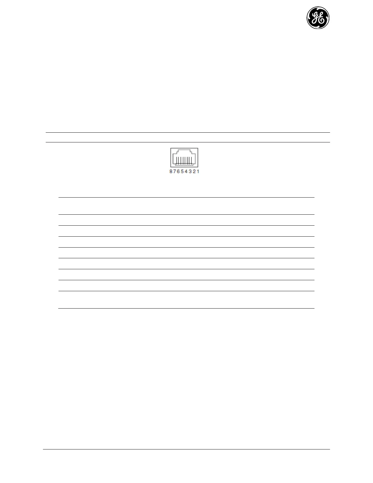
The tables on the following page provide pin descriptions for the COM1 data port in RS-232 mode and
RS-485 modes, respectively.
NOTE The COM2 port, if present, is restricted to RS-232 mode; it cannot be used for RS-485.
(As viewed from the outside the unit)
Table 2-2. COM1/2 Port Pin Details (RS-232)
COM1 only: ALARM Output (refer to “Alarms” on Page 150 )
DCD (Data Carrier Detect)
Connects to ground (negative supply potential) on chassis
RXD (Received Data)—Supplies received data to the connected device
TXD (Transmitted Data)—Accepts TX data from the connected device
 Loading...