MDS 05-6632A01, Rev. F MDS Orbit MCR/ECR Technical Manual 31
2.8 Antenna Planning and Installation
Consideration must be taken to select appropriate antennas for optimal RF performance. This section
reviews the key factors involved in selecting and installing antennas for the Orbit MCR and ECR. Only
approved antennas may be used on the unit’s RF output connectors. These antennas are listed in each
applicable section for each RF type. The use of non-approved antennas may result in a violation of FCC
rules and subject the user to FCC enforcement action.
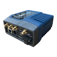
Cell Antennas (Aux and Main)—These SMA coaxial connectors are for attachment of cellular antennas.
The MAIN connection is for basic cellular transmission/reception and the AUX connector is for
attachment of a receive-only antenna which provides MIMO receive operation (diversity) with standard
Cell modules, improving signal quality in many installations. In general, both antennas should always be
used for cellular operation. The GE MDS part number for this antenna type is 97-2485A04.
Figure 2-10. Directly-Connected Cellular Antenna (Typical Style)
(GE MDS Part No. 97-2485A04)
WiFi Antenna—Antenna connection for 2.4 GHz WiFi service. The connector appears similar to the
cellular connectors discussed above, but is a Reverse-SMA type. It contains a pin that matches with an
SMA-F connector. The GE MDS part number for this antenna is 97-4278A34.
To connect an external WiFi antenna, 97-4278A48, a Reverse SMA to N-Female cable and antenna
mount is required. These are not sold from GE MDS but are available from many retailers.
900 MHz ISM Antennas —Antenna connection is a TNC connector. Multiple options are available for
this unlicensed operation.
NOTE For 900MHz ISM operation (NX915 NIC) professional installation is required.
NOTE For Australia and New Zealand the maximum EIRP must be limited to 30 dBm. If ((antenna
gain - feed line loss) + power output setting) > 30), then the power output of the
NX915 must be reduced.
NOTE For regions governed by FCC/IC compliance the maximum EIRP must be limited to 36 dBm. If
((antenna gain - feed line loss) + power output setting) >36), then the power
output of the NX915 must be reduced.
Licensed Narrowband Antennas —Antenna connection is a TNC connector. Multiple options are
available based on radio type and site-specific licensing rules.
 Loading...